


POWDERS IN BULK
Page 74
Page 75
Page 76
If you've noticed an error in this article please click here to report it so we can fix it.
A day operating the 30-ton-gross Crane Fruehauf hopper vehicle
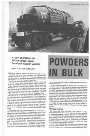
By R. D. CATER, AMInstBE AR by year more powdered and granular materials are traits ported in bulk rather than in packages. Few companies build complete vehicles for any given type of specialized transport, but one that stands out among the manufacturers of semi-trailers for special purposes is Crane Fruehauf Trailers Ltd.
One of the latest units produced by this company is the 850 Cu. ft. bulk powder vehicle that was recently lent to COMMERCIAL MOTOR for evaluation. The results obtained, with the semi-trailer coupled to an AEC Mandator with Ergomatic cab and an AV 691 diesel engine, were encouraging from the point of view of turn round time and cleanliness of operation. But, at the opposite end of the scale, it proved to be a bit of a handful to manoeuvre in a confined space, which after all is the usual setting for this class of work.
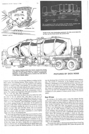
The semi-trailer is constructed throughout in electrically welded mild steel sheet. In the main the sheeting is of 10 s.w.g., but parts of the end cones—which are purely a means of supporting the actual hopper section—are of 12 s.w.g. At first glance the fact that these fairly large end-sections have no value other than to support the centre section, seems to be a considerable waste of unladen weight. It must be remembered, however, that the necessary outer-axle spread of 32 ft. must be obtained to operate at 30 tons gross and this is by far the lightest means of obtaining the required overall length.
Running-gear and fifth-wheel rubbing-plate are mounted direct on to the tank shell and there is no chassis frame. Cargo is contained in the hopper section of the tank which has slope sheets placed on a line commencing at the centre of the aeration, or fluidizing pads, and running up to the top of the tank at an angle of 50°.
At both the front and rear end baffles, these slope sheets form the shape of a chute, directing the flow ofmaterials down to the fluidizing pads. The actual diameter of the fluidizing pads is 15.125 in. and these are sloped down towards the 5 in. diameter product outlet at 250 from the horizontal. The product outlet pipe is carried on downwards at this angle until it joins with the air flow-line and this section can be closed by a butterfly valve which is inserted between the pads and the air flow-line.
At each end of the section of the tank having the full diameter, and at two points centrally between the first and second, and second and third hoppers, a reinforcing ring manufactured from 10 s.w.g. completely encircles the unit. At a position central to each fluidizing pad, and to the point where the slope sheets project through the main tank shell, three more reinforcing part-rings are fitted. These extend around the tank as far down as another reinforcing member running longitudinally that is also manufactured from 10 s.w.g. top-hat section mild steel. Thus the whole of the pressurized section of the hopper is suitably braced against the required pressure of 15 p.s.i.
Throughout the length of the tank, seam positions are staggered by reversing the sheets in each section in the standard manner. In the end cones the plate is stiffened with tapered mild-steel channel sections.
Advantage in service The running-gear is the well known Crane Fruehauf F2 type, having a T section sub-frame, the T being inverted to allow mounting by mating with a similar T section, this time the correct way up, each vertical leg of the T nestling alongside its companion and being bolted through to secure. The big advantage of this mounting is in the facility offered to easily "nip up" the securing bolts when the vehicle is in service, an operation not always possible when using the conventional flange to flange mounting.
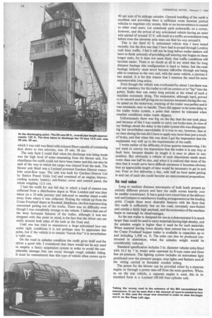
Access to the tank for loading is via three manlids, each having a full 20 in. diameter opening. The lids are secured by six over-centre cam-locks (equipped with screw adjusters) equidistant around them. I found the locks easy to use and most efficient in holding the lids down against the working pressure. When loading a fairly heavy substance it is necessary only to use one manhole to get sufficient material on board to make a full payload. If a less dense material is to be carried which will entail using the full capacity of the tank then all three lids will need to be used. Each manlid is situated immediately above the fluidizing pad of the compartment which it serves. This enables easy inspection of the pads and permits a check that the load has been fully discharged.
Two pressure relief valves are fitted, one in the shell of the tank, the other in the air pressure line. Also fitted in this line is a non-return valve to prevent cargo being blown back into the compressor in the event of the engine stopping during discharge. Cargo valves are of the "Keystone" type comprising a butterfly mounted on a spindle passing through the valve body. On the spindle is an operating handle which carries a ratchet lever connected to a ratchet and pawl mechanism, enabling the valve to be set at any chosen position between fully open and fully closed. This is an essential feature of bulk powder or granular transport for it is necessary that the pressure within the tank is controlled to a level slightly higher than that on the discharge line.
To discharge the product the cargo space is pressurized by pumping air through fabric pads situated in the bottom of each hopper. The action of the air passing through these pads causes the material in the immediate area to be suspended in a turbulence of air, so becoming fluidized. When sufficient pressure has been accumulated in the cargo space, the valves, closing first one compartment and then the others in turn, are opened allowing the slightly higher pressure in the tank to press the fluidized portion of the cargo down into the discharge line to be blown away up the customer's delivery pipe. The process is continuous: as the fluidized portion of the material is discharged so the less fluidized portions come into contact with the pads, and so on, until the tank is empty. The pressure within the tank remains almost constant throughout the operation, the volume of compressed air increasing as the cargo is decreased. When the test load was discharged the tank was cleared with the . exception of a few pounds of cement powder lying on the bottom plates.
Over 28 tons
On arriving at the loading point a snag that plagues the dry bulk product carrier was soon apparent. I asked the loader how he knew what weight was being loaded; he replied that he did not, but that I should. Fortunately, other members of our party knew and the tank was duly laden with what was guessed to be the required 18 tons 11 cwt. Returning to the weighbridge we found that it could not take just the trailer because it scaled over 28 tons! Officials of the company that provided the test load told me that all new plants were being constructed with a weighbridge under the loading point, which will overcome this problem. I could not help concluding, however, that something should be devised in the meantime to enable a strange driver to check what weight he was putting on board, if only to ensure that the maximum load was carried on every journey without having to resort to vehicles being driven back and forth to the weighbridge.
The actual time taken to discharge the load of 19 ton 14 cwt 2 qr. into a hopper situated approximately 90 ft. above the ground. and which I was told was fitted with exhaust filters capable of containing dust down to two microns, was 39 min. 38 sec.
The only fault I could find when the discharge was being made was the high level of noise emanating from the blower unit. For cleanliness the outfit could not have been better and this can also be said of the way in which the cargo was cleared from the tank. The blower unit fitted was a Leyland powered Gardner-Denver rotarylobe axial-flow type. The unit was built for Gardner-Denver Ltd by Sutton Power Units Ltd and consisted of an engine; blower; cooling system; battery; sub-frame; cover and control panel, the whole weighing 12.5 cwt.
I had the outfit for one full day in which a load of cement was collected from a distribution depot in West London and was then taken on a 35-mile journey and delivered to another depot a mile away from where it was collected. Picking the vehicle up from the Crane Fruehauf depot at Southall, Middlesex, the first manoeuvring concerned getting out of the works. There was no difficulty even though I was completely strange to the vehicle. I believe that one of the most fortunate features of the trailer, although it was not designed with this point in mind, is the fact that the driver can see easily around both sides of the tank at the front end.
Until one has tried to manoeuvre a large articulated box-van under tight conditions it is not perhaps easy to appreciate this point, but if the vehicle is to remain "knock-free" it is nevertheless a'valid one. '
On the road in unladen condition the outfit gives itself and the driver a good ride. I considered that there would not be any need to employ a fancy suspension system in order to avoid the considerable damage that can occur through rough unladen riding. It must be remembered that this type of vehicle often covers up to 50 per cent of its mileage unladen. General handling of the outfit is excellent and providing there is sufficient room between parked vehicles to negotiate city streets, little or no inconvenience is caused to other road users. Let somebody park awkwardly on a comer, however, and the arrival of any articulated vehicle having an outer axle spread of around 35 ft. will result in a traffic accumulation long before even the cleverest attic man can find his way around it.
This is the third 42 ft. articulated vehicle that I have tested recently, but the first one that I have had to propel through London rush hour traffic. I feel it will not be long before trailer makers will have to think seriously of providing self-steering rear bogies on these longer units, for it does not seem likely that traffic conditions will become easier. There is no doubt at all in my mind that for long distance haulage this configuration is hard to better, but the road haulage industry must never become inflexible through not being able to continue to the very end, with the same vehicle, a journey it has started. It is for this reason that I mention the need for more manoeuvrable long-artics.
Even though the vehicle was overloaded by about 1 ton there was not any tendency for the trailer to roll on corners or to "lay" into the gutter, faults that can make long periods at the wheel of such a machine extremely tiring. The suspension, although hard, proved to be smooth and stiff giving me no anxious moments during the run. At speed on the motorway, tracking of the trailer was perfect and it was extremely easy to handle. There did appear to be some delay in the trailer brake system, a point that cannot be tolerated when weather conditions make roads slippery.
Unfortunately there was fog on the day that the test took place and because of this I was unable to carry out brake tests. In view of my feelings about the delay in the trailer system this was disappointing but nevertheless unavoidable. It is true to say, however, that at no time during the test did I have to apply any more than just a touch of brake, and that when this was done I got the impression that the equipment was well up to the requirements of the outfit.
I wrote earlier of the difficulty of close-quarter manoeuvring. I do not want to convey the impression that the trailer is in any way at fault here, because despite its length it is easy to place in any position. But obviously a vehicle of such dimensions needs more room than one half its size, and when it is realized that most of the sites that it would serve have difficult entrances it becomes obvious that an appreciable length of time would be necessary to get in and out. Four or five deliveries a day, with half an hour spent getting in and out of each site could become an uneconomical proposition.
Its real value
Long or medium distance movements of bulk loads present an entirely different picture and here the outfit scores heavily over its smaller counterpart. It has a quick turn round time at the delivery end and (subject to satisfactory loading arrangements) at the loading point. Couple these most desirable features with the facts that this outfit is sufficiently fast on the road, extremely sure-footed and carries a fairly high payload, and the economics of the machine begin to outweigh its disadvantages.
As the test trailer is designed for use as a demonstrator it is much larger than could be used to carry materials having high density, and the unladen weight is higher than it need be for such materials. When material having lower density than cement has to be carried the Crane Fruehauf hopper trailer is available in capacities up to and including 1,500 Cu. ft. The units can also be produced constructed in aluminium, when the unladen weight would be considerably reduced.
Standard specification includes 5 in. diameter tubular axles fitted with 16.5 by 7 in. brake units operated by S-type cams and three line air-pressure. The lighting system includes an instrunient light positioned over the pressure gauges, stop lights and flashers and all the wiring carried in threaded conduit tubing.
The power for the blower can be provided either by a separate engine or through a power take-off from the main gearbox. When, as on the test vehicle, a separate engine is used, this in its standard form is a Leyland 0E160 four-cylinder unit.