


A Suspension Stabilizing Device
Page 74
If you've noticed an error in this article please click here to report it so we can fix it.
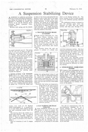
ASCHEME for positively preventing sway during cornering by hydraulically tilting the chassis in the opposite direction is described in patent No. 720,551, by E. and W. Newton, 44-45 Lancaster Mews, Lancaster Gate, London, W.2.
Between each spring, and the chassis is a small hydraulic ram (1). The spring and the ram are in series so that the spring can still function when the ram is extended. The four rams are piped to a gearbox-driven pump (2) and are fed with liquid thereby, subject to the control of a distributor valve.
Normally, the rams are unextended, but when the steering column is turned, the control valve (3) is operated. This causes the rams to rise on the outside pair of wheels and so maintain the body level, even though the springs deflect The control valve does not come into operation until the steering angle exceeds five degrees.
A QUICK-ACTING CAB WINDOW
THaEdriver of a large vehicle needs very convenient and quick-acting window both for the giving of handsignals and for leaning out when reversing. Designed with these requirements in view, are a window and frame shown in patent No. 717,278 (W. Small and
Auster, Ltd., both of 174 Barford Street, Birmingham, 5). A second aim is to meet these needs without having any part projecting unduly from the body.
The drawing shows the window in a partly open position. The two vertical glass panels are mutually hinged at point 1. They are also joined by linkage 2 which is pivoted to the frame at point 3.
Pairs of trunnions (4 and 5) engage K34 in slots in the frames and guide the two panels in such a path that as the angle between them diminishes they move bodily leftwards. In the extreme open position, the panels lie at right-angles to the frame, thus allowing ample room for the driver to signal or make a rearward inspection, A single movement will close both panels practically flush with the outside of the body.
A TRACTOR-TRAILER BRAKE ACCESSORY FROM Clayton Dewandre Co., Ltd., Titanic Works, Lincoln, comes patent No. 720,562, dealing with a valve device for incorporating in a tractortrailer braking system. Its aim is to isolate the tractor system in tle event of the trailer breaking adrift, so that the tractor power-brakes still remain operative.
The drawing shows the unit employed; it consists of a block con taming two spring-closed valves (1 and 2). One of these is interposed between the pedal-valve passage (3) and the trailer-brake connection (4). The other valve controls the connection (5) to the main reservoir and one (6) to the trailer reservoir. , Normally, the valves are inoperative, being held in the open position by flange 7 of a metal bellows (8); the latter is upwardly expanded when the normal reservoir pressure reaches it via the passage (9). If, however, a breakaway should occur, the drop in pressure on the trailer side causes the bellows to shorten and close both valves. This completely isolates the tractor braking system from the defective portion. , A GAS TURBINE FOR ROAD VEHICLES
A GAS TURBINE suitable for road i't vehicles is shown in patent No. 720,436, by A. de Kezdivasarhely, 176 Boulevard Haussmann, Paris. The chief novelty is that the turbine volutes are not provided with stationary guidevanes; instead, the two turbines are arranged to on in opposite directions.
Referring To the drawing, the aircompressor (1) is mounted on the same
shaft as its driving turbine (2). The power turbine (3) has its shaft brought out to the reduction gearing indicated at 4.
The combustion system is unusual in that the burning gases from the chamber (5) meet, first, the output turbine and then pass through it to
work the compressor turbine. The final exhaust from this unit is passed through a heat-exchanger (6) Which raises the temperature of the ingoing air. The fuel and oil pumps (7) are driven by the shaft of the compressor.
The patent also describes certain cooling arrangements which enable the revolving. parts to be made a much closer fit to the casing than is usual, thus increasing the efficiency 4'1-educing leakage.
A DAIMLER-BENZ COMBUSTION SYSTEM
TO improve fuel consumption and to give quieter running, are the two objects of an oil-engine combustion' system shown in patent No. 717,215 (Daimler-Benz A.G., Stuttgart-Unterturkheirn, Germany). The scheme describedtises a pre-combustion chamber in the, head and a spherical air-cell, or vortex chamber as it is termed, in the crown of the piston.
. The cell (1) communicates with the pre-combustion chamber (2) via a
narrow passage (3). The .piston is otherwise a very close. fit to the head. On the" compression stroke, the air in the cell iS whirled in an anti-clockwise direction, but immediately after injection commences, the flaming jet issuing from the pre-combustion chamber reverses the direction of swirl, and in doing so. causes a very intimate mixture of Air and fuel.