


Self changing Gearbox Controlled by Speed and Torque
Page 36
If you've noticed an error in this article please click here to report it so we can fix it.
A Résumé of Patent Specifica. lions That Have Recently Been Published
BEARING the name Wind
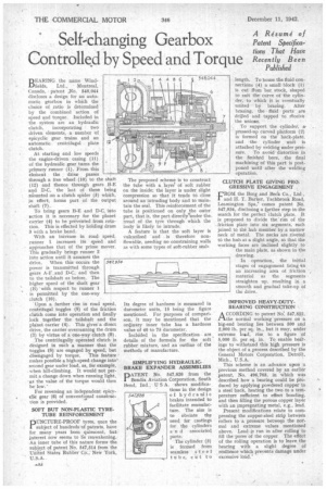
fields, Ltd., Montreal, Canada, patent ,No. 548,044 discloses a design for an automatic gearbox in which the choice of ratio is determined by the combined action of speed and torque. Included in the sistem are an hydraulic clutch, incorporating two driven elements, a number of epicyclie gear trains and an automatic centrifugal plate clutch.
At starting and low speeds the engine-driven casing (11) of the hydraulic gear turns the primary runner (1). From this eleinent the drive passes through a free wheel (10) to the shaft (12) and thence through gears P-E and D.C. the last of these being Mounted on a clutch spider (5) whieh, in effect, forms part of the output shaft (7).
To bring gears B-E and D-C, into action it is necessary •for the planet carrier (4) to be prevented from rotation. This is effected by holding drum 3 with a brake band.
With an increase in road speed, runner 1 increases its speed and approaches that of the prime mover.
This gradually brings runner 2 into action until it assumes the drive. When this occurs the power is transmitted through gears A-F and D-C, and then to the tailshaft as before. The higher speed of the shaft gear (B) with respect to runner 1 is permitted by the one-way zlutch (10).
Upon a further rise in road speed, centrifugal toggles (8) of the friction clutch come into operation and finally lock together the tailshaft and the planet carrier (4). This gives' a direct drive, the carrier overrunning the drum (3) by virtue of a one-way clutch (9).
The centrifugally operated clutch is designed in such a manner that the toggles (8) are engaged by speed, but disengaged by torque. This feature makes possible a high-speed change into' second gear under load, as, for example, when hill-climbing. It would not permit a change down when running light, as the value of the torque would then be low.'
For reversing an independent epicy
• clic gear (6) of conventioonal construetion is provided.
SOFT BUT NON-PLASTIC TYRETUBE REINFORCEMENT PUNCTURE-PROOF tyres, once the subject of hundreds of patents, have for many years been quiescent, but interest now seems to be reawakening. An inner tube of this nature forms the subject of patent No. 547,514 from the United States Rubber Co., New York, U.S.A.
The proposed scheme is to construct the tube with a layei' of soft rubber on the inside; the layer is under slight compression so that it tends to close around an intruding body and to maintain the seal. This reinforcement of the tube is positioned on only the outer part, that is, the part directly‘under the. tread of the tyre through which the body is likely to intrude.
A feature is that the soft layer is vulcanized and is therefore nonflowable, needing no constraining walls as with some types of soft-rubber seals Its degree of hardness is measured in durometer units, 15 being the figure mentioned. For purposes of comparison, it may be mentioned that the ordinary inner tube has a hardness value of 40 to 75 durometer.
Inchided in the specification are s details of the formula for the .soft rubber mixture, and an outline of the methods of manufacture.
SIMPLIFYING HYDRAULIC. BRAKE EXPANDER ASSEMBLIES DATENT No. 547,826 from the Bendix Aviation Corporation, South Bend, Ind., U S A. shows modifica tions in the design of hydraulic brakes intended to facilitate manufacture. The aim is to obviate the need for castings for the cylinders a n d associated, parts.
The cylinder. (3) is formed from seamless steel • tube, cult to length. To house the fluid connections (4) a small block (1) is cut fham bar stock, shaped to suit the. curve of the cylinder, to which it is eventually united by brazing. After brazing, the fluid ports are drilled and tapped to rbceive the unions.
. To support the cylinder, ar pressed-up curved platform (2) is formed on 'the back-plate, and .the cylinder unit is attached by welding under pressure. To avoid distortion in the finished bore, the final machining of this part is postponed until after the welding operation, CLUTCH PLATE GIVING PROGRESSIVE ENGAGEMENT FR9M the Borg and Beck Co., Ltd. and H. T. Barker, Tachbrook Road. Leamington Spa, comes patent No. 547,934, disclosing a further step in the search for the perfect clutch plate. It is proposed to divide the" rim of the friction plate into six segments, each joined to the hub member by a narrow neck of metal. The necks are riveted to the hub at a slight angle, so that the working faces are inclined slightly to the main plate, as shown in the drawing.
In operation, the initial stages of engagement bring n an increasing area of friction material as the segments straighten up. resulting in a smooth and gradual take-up of the drive.
IMPROVED HEAVY-DUTYBEARING CONSTRUCTION A CCORDING to patent No 547,852, 1-tthe normal working pressure on a big-end bearing lies between 500 and 2,000 lb. per sq. in., but it may, under extreme load, rise to a figure of 5,000 lb. per sq. in. To enable bearings to withstand this high pressure is the object of a process described by the General Motors Corporation, Detroit, Mich., U.S.A.
This scheme is an advance upon -a previous method covered by an earlier patent, No. 496,763, in which wns described how a bearing could be produced by applying powdered copper to a steel back, heating the two to a temperature sufficient to effect bonding. and then filling the porous copper layer with an impregnating metal, e.g., lead.
Present modifications relate to compressing the copper-steel strip between rollers to a pressure between the normal and extreme values mentioned above. Lead run in after rolling to fill the pores of the copper The effect of the rolling operation is to leave the bearing with a slight degree of , resilience which prevents damage under excessive load.'