


ASSEMBLING A MOTOR COACH WIRELESS SET.
Page 24
Page 25
If you've noticed an error in this article please click here to report it so we can fix it.
The Requirements of a Good Receiver for Motor Coach Reception were Outlined Last Week. We go on now to a Consideration of the Theoretical Diagram.
IN THE first article of this new constructional aeries, which commenced in last week's Commercial Motor, we briefly recapitulated the considerations that underlie the design of a receiver for motor coach work. We showed that the conflicting attributes of compactness, eas6 of handling and high efficiency had all to be met by a series of compromises, and we noted that it was on the care and forethought displayed in the making of these compromises that the success of the receiver depended.
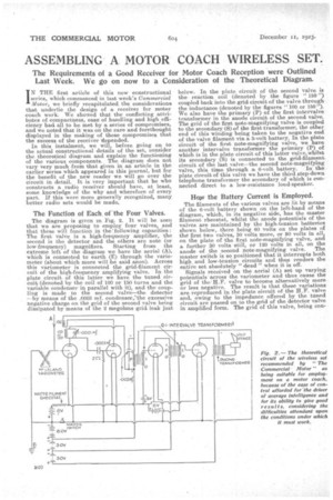
In this instalment, we will, before going on to the actual constructional details of the set, consider the theoretical diagram. and explain the functioning of the various components. The diagram does not vary very much from that given in an article in the earlier series which appeared in this journal, but for the benefit of the new reader we will go over the circuit in detail. It is very important that he who constructs a radio receiver should have, at least, some knowledge of the why and wherefore of every part. If this were more generally recognized, many better radio seta would be made,
The Function of Each of theFour Valves.
The diagram is given in Fig. 2. It will be seen that we are proposing to employ four valves, and that these will function in the:following capacities : The first valve is a high-frequency amplifier, the second is the detector and the others are note (or low-frequency) magnifiers. Starting from the extreme left of the diagram we have the aerial (A), which is connected to earth (E) through the variometer (about which more will be said anon). Across this variameter is connected the grid-filament circuit of the high-frequency amplifying valve. In the plate circuit of this latter we have the tuned circuit, (denoted by the coil of 100 or 150 turns and the variable condenser in parallel with it), and the coupling is made to the second valve—the detector —by means• of the .0003 mf. condenser:the excessive negative charge on the grid of the second valve being dissipated by means of the 2 megohms grid leak just
below. In the plate circuit of the second valve is the reaction coil (denoted by the figure "150 ") coupled back into the grid circuit of the valve through the inductance (denoted by the figures "100 or 150"). We also have the primary (P) of the first intervalve transformer in the anode circuit of the second valve. The grid of the first note-magnifying valve is coupled to the secondary (5) of the first transformer, the other end of this winding being taken to the negative end of the valve filament via a 3-volt battery. In the plate circuit of the first note-magnifying valve, we have another intervalve transformer the primary (P) of which is in the plate circuit of this latter valve, whilst its secondary (S) is connected to the grid-filament circuit of the last valve—the second note-magnifying valve, this time through a. 6-volt battery. In the plate circuit of this valve we have the third step-down telephone transformer the secondary of which is connected direct to a low-resistance loud-speaker.
Hop the Battery Current is Employed.
The filaments of the various valves are lit by means of the 6-volt battery shown on the left-hand of the diagram, which, in its negative side, has the master filament rheostat, whilst the anode potentials of the valves are maintained by the high-tension batteries shown below, there being 60 volts on the plates of the first two valves, 30 volts more, or 90 volts in all, on the plate of the first note-magnifying valve, and a further 30 volts still, or 120 volts in all, on the anode of the second note-magnifying valve. The master switch is so positioned that it interrupts both high and low-tension circuits and thus renders the entire set absolutely " dead " when it is off. Signals received on the aerial (A) set up varying potentials across the variemeter and thus cause the grid of the H.F. valve to become alternatively more or less negative. The result is that these variations are reproduced in the plate circuit of the H.F. valve and, owing to the impedance offered by the tuned circuit are passed on to the grid of the detector valve in amplified form, The grid of this valve, being con trolled in static potential by means of the grid leak, causes lopsided, or as we call them, rectified (although the former is the truer description) currents to traverse the plate circuit of the valve. These rectified currents pass through the primary of the first intervalve transformer, whilst the high-frequency components pass through the by-pass condenser in parallel with it. These latter, in traversing the reaction coil, act back upon the inductance and thus boost up the plate currents from the H.F. valve (which are the currents operating the grid of the detector valve). The rectified portion of the output of the detector valve, which. is now at speech frequency, is transformed or stepped up in voltage and applied to the grid of the first note-magnifying valve, to appear in magnified form in the plate circuit of this valve, wherein is the primary of the second intervalve transformer.
The speech currents are again stepped up in voltage and applied to the second note-magnifying. valve only to appear once more magnified in the anode circuit of this last valve. The currents now traverse the primary of the telephone transformer and are stepped down in voltage and applied to the low-resistance loud-speaker, causing the latter to sound.
The master filament rheostat is, as we have said, placed it the negative lead of the low-tension battery. its sole function in this particular set is to enable adjustment and compensation to be made for falling voltage in the low-tension battery as the latter becomes discharged in use. No separate filament resistances are fitted to individual valves, since, for the sake of utmost simplicity in operation,, these can be omitted without serious detriment to efficiency.
The different plate potentials on the various valves are necessary to give a good volume of sound in the loud-speaker without distortion, as are also the 3-volt and 6-volt grid batteries in series with the secondary windings of the first and second intervalve trans formers. The exact reason for this will be more fully dealt with in a subsequent article.