


VARIETY IN -TRACTOR-VEHICLE DESIGN.
Page 13
Page 14
If you've noticed an error in this article please click here to report it so we can fix it.
Some Thoughts Arising Out of a Study and a Comparison of the Different Types of Six-wheeled Articulated Vehicles on the Market.
THE development of the various types of large load carriers on six wheels, as was foreshadowed in the columns of this journal, which pioneered the movement, has proceeded apace—in fact, so fast that suitable names have not yet been found for the types. The terms tractor-lorry, tractor-van, tractor-tipper and tractor-bus are applicable to the self-contained or complete vehicles in which the tractor and the load carrier are, in ordinary usage, never separated. The other classification embraces the machines in which the load carrier is detachable from the tractor, and this, again, is divisible into two classes, in one of which is included those vehicles which are movable after detachment and those which are not. We deal with these farther on in the. article.
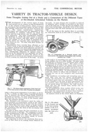
Opportunities have recently been afforded us for a careful study of this development as a whole, and to compare methods and ideas adopted and held by designers, and some very interesting comparisons can be drawn. For instance, taking turntable construction, considerable difference of opinion seems to exist as to the desirability of a perfectly free movement of the turntable, to allow the wheels of the rear portion to mount an unevenness of road surface without causing any distortion of the body. In some cases, a three-point suspension is provided, as shown in Fig. 1, whilst, in other cases, a partial movement only is allowed, the pivotal action being controlled by means of springs. In some instances there is no provision for the roll or twist of the chassis, other than the ordinary springs.
The Scammell and Carrimore must be taken as good examples of construction, owing to the experience these manufacturers have had and the pioneer work which they have done, which no doubt enables them to steer clear of many of the pitfalls into which the newcomers into the field of the six-wheeler will be likely to fall.
In each of these types the free movement is controlled by means of springs. The argument in favour of this arrangement is that an uncontrolled and perfectly free provision for side roll decreases the stability of the load to a point which, in certain circumstances, becomes dangerous. The argument in favour of a perfectly free movement is that there is no racking strain whatever on the body. In some designs the turntable is reduced in diameter and a spring is provided at the lower end of the king pin, so that the pin can slightly withdraw from its bearings, should the twist of the frame become more than the main springs can conveniently take.
In all the types on the market there is provision for distortion such as is met with in crossing a dip in the road or in travelling over such a mound as the steep,. sudden rise of a canal bridge. In some cases the kmg pin is mounted on a horizontal slide, which is controlled by spring buffers. The object of this arrangement is to relieve the shock when starting. It often happens that a six-wheeled tractor-lorry is required to detach its rear portion and to be able to couple up another similar portion, so as to save time in loading and unloading. In some makes this is provided for, whilst in others the six-wheeler is only intended for use as one complete and unalterable machine.
The conditions of loading and unloading vary so much that even the two classes of c six-wheeler, namely, the detachable and the non-detachable, can be divided again into, two sub-classes. With regard to the machines in the first of these sub-classes, the rear portion, when separated from the power unit, can be moved about on wheels ; the load carriers, which fall into the second class, merely rest on stationary supports.
In all probability, those models which to-day are non-detachable will eventually be made in such a form that the requirements of those whose business demands a detachable rear portion can be met. As matters stood at the recent Show at Olympia,
those six-wheelers which did not provide for the detachment of the load were as In low :— Scammell, Hallford, Carrimo e (bus Sentinel, and Longframe. Those in which the load-carryin portion can be detached were the A.E.C., *Auto Tractor, G.M.C., Carrimore lorry, *G. V. Elect ic, *Eagle, and *Renault.
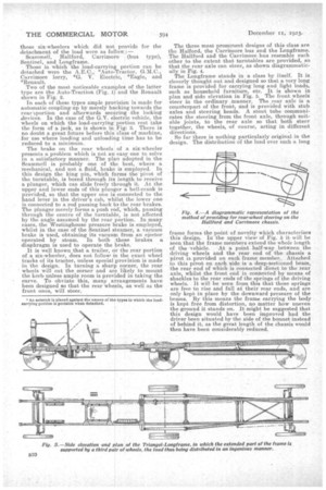
Two of the most noticeable exaiiples of the latter type are the Auto-Traction (Fig. 1 and the Renault shown in Fig. 2.
In each of these types ample pro ision is made for automatic coupling-up by merely b eking towards the rear eportion and afterwards sec ring .the locking .devices. In the case of the G.V. e H trio vehicle, the wheels on which the load-carrying portion rest take the form of a jack, as is shown inFig: 3. There is no doubt a great future before this class of machine, for use where loading and unloadi g time has to be reduced to a minimum.
Thebrake on the rear wheels of a six-wheeler presents a 'problem which is not an easy one to solve in a satisfactory manner. The pl a adopted in the Scammell is probably one of tie best, where a mechanical, and not a fluid, brak is employed. In this design the king pin, which firms the pivot of the turntable, is bored through it length to receive a plunger, which can slide freely t rough it. At the upper and lower ends of this plun er a bell-crank is provided, so that the upper one i connected to the hand lever in the driver's cab, w ilst the lower one is connected to a rod passing back o the rear brakes. The plunger merely forms a push $d, which, passing through the centre of the turntab e, is not affected by the angle assumed by the rear portion. In many cases, the Westinghouse pressure lrake is employed, whilst in the case of the Sentinel siteamer, a vacuum brake is used, obtaining its vacuuitn from an ejector operated by steam. In both these brakes a diaphragm is used to operate the frake. It is well known_that a trailer, r the rear portion of a six-wheeler, does not follow ii the exact wheel tracks of its tractor, unless special provision is made in the design. In turning a sharp corner, the rear wheels will cut the corner and are likely to mount the kerb unless ample room is provided in taking the curve. To obviate this, many a rangements have been designed so that the rear whe Is, as well as the front ones, will steer.
type),
The three most prominent designs of this class are the Halford, the Carrimore bus and the Longframe. The Hallford and the Carrimore bus resemble each other to the extent that turntables are provided, so that the rear axle can steer, as shown diagrammatically in Fig. 4. The Longfrarne stands in a class by itself. It is cleverly thought out and designed so that a very long frame is provided for carrying long and light loads, such as household furniture, etc. It is shown in plan and side elevation in Fig. 5. The front wheels steer in the ordinary manner. The rear axle is a counterpart of the front, and is provided with stub axles and steering heads. A stout tube communicates the steering from the front axle, through suitable joints, to the rear axle so that both steer together, the wheels, of course, acting in different directions.
So far there is nothing particularly original in the design. The distribution of the load over such a long
frame forms the point of novelty which characterizes this design. In the upper view of Fig. 5 it will be seen that the frame members extend the whole length of the vehicle. At a point half-way between the driving wheels and the rear end of the chassis a pivot is provided on each frame member. Attached to this pivot on each side is a deep-sectioned beam, the rear end of which is connected direct to the rear axle, whilst the front end is connected by means of shackles to the rear ends of the springs of the driving wheels. It will be seen from this that these springs are free to rise and fall at their rear ends, and are only kept in place by the downward pressure of the beams. By this means the frame carrying the body is kept free from distortion, no matter how uneven the ground it stands on. It might be suggested that this design would have been improved had the driver been situated by the side of the bonnet instead of behind it, as the great length of the chassis would then have been considerably reduced.