


The Use of Compressed Air for Chassis Suspension
Page 47
If you've noticed an error in this article please click here to report it so we can fix it.
THE combination of pneumatic tyres and steel springing, as now almost exclusively used for commercial vehicles, admittedly has its limitations. It can, however, easily be improved by making a second use of air, although in a somewhat different manner. Tests by Tibrometer are claimed by the maker of the Gruss air spring, which costs for a medium-size vehicle in the neighbourhood of £20, to show that this device eliminates from 50 to 70 per cent, of road shocks.
Normally interposed between the elumbirons and the ends of the front springs, these air springs afford an extremely sensitive, yet progressive, springing action. Furthermore, this is combined with a damping effect which controls the freedom of motion that might otherwise result in bouncing.
Under the most exacting conditions of cross-country work overseas, we understand that they have given entire satisfaction. Two prominent users are the British Government and the Iraq Petroleum Co., Ltd., and we are informed that the former has standardized Gruss springs on certain vehicles.
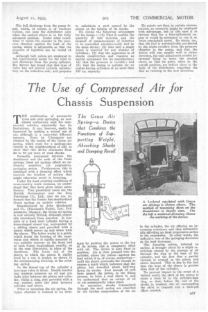
Manufactured by John Macdonald and Co. (Pneumatic Tools), Ltd., Pollokshaws, Glasgow, the Gruss air spring is now entirely British, although originally introduced from America. It consists of a fixed steel cylinder having a dome-shaped closed top, surrounded by a sliding sleeve and provided with a piston which moves up and down with the sleeve. The latter works in a guide, which forms the housing of the apparatus and which is rigidly mounted in any suitable manner on the front end of each frame longitudinal, usually, as in the case illustrated, in place of the dumbiron. The lower end of the eleeve, to which the piston is rigidly fixed by a rod, is hinged, as shown in the accompanying drawing, to the existing spring.
In the domed top of the cylinder a tyre-type valve is fitted. Double leather cup washers preserve an oil and airtight joint between the piston and cylinder, whilst a ring, also provided with a cup washer, seals the joint between cylinder and sleeve.
Prior to mounting the air spring, the Upper chamber is reduced to its mini mum by pushing the piston to the top of its stroke, and is completely filled with oil. The device is next fixed in position. Air is then pumped into the cylinder, above the piston—against the load which it is, of C0111"Se, supporting— until the sleeve protrudes far enough to expose a mark which indicates that the piston has travelled about half-way down its stroke. Just enough oil will have passed the piston, in the filling process, to form a seal above it, and we understand that no escape of oil or air subsequently takes place.
In operation, shocks transmitted through the steel spring are absorbed by the further compression of the air in the cylinder, the air offering an increasing resistance and thus automatically affording an ideal progressive action to the suspension. In other words, the deflection rate of the springing decreases as the load increases.
The damping action, referred to earlier, is brought about by a slight restriction caused by the passage of oil through the ring at the base of the cylinder, and the fact that a partial vacuum is created as the piston and sleeve descend. This is due to the fact that the bore of the sleeve is greater than that of the cylinder.
To prevent impact in the event of a violent recoil, the skirt of the piston is made a close fit in the cylinder-base ring, so that, before the end of the stroke is reached, the oil surrounding the skirt is trapped and a dash-pot effect created.