Useful Charts and Tables. No. 8.
Page 57

If you've noticed an error in this article please click here to report it so we can fix it.
By George Watson, A.M,I.Mech.E.
Bevel Gear Design.
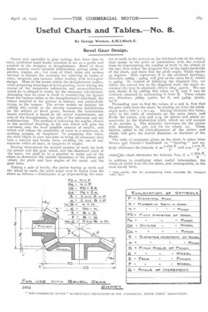
Nearly ever specialist in gear cutting, has, from time to Etime, published hand books intended to act as a guide and .comfort to the designer or draughtsman. Some of these books contain much valuable information, giving tables of pitches, angles, etc., but none of them make any serious attempt to obviate the necessity for referring to tables of sines, tangents and cosines, when dealing with bevel-gear -design. Most of the errors which the draughtsman makes, when preparing drawings of bevel gearing, occur during the course of the numerous references and cross-references, which he is obliged to make, for the necessary calculations. Assuming that no error is made in transferring the figures from the various tables to the draughtsman's note-book, the labour entailed in the process is tedious, and particularly trying to the temper. The writer makes no apology for adding this article to the already numerous publications -on the subject of bevel gears, because the information herein contained is based on the actual requirements, not .only of the draughtsman, but also of the toot-room and the .machine-shop. The method of indicating the angles, shown in the sectional drawing, is the one which will give the tool-room men the least possible amount of trouble, and .which will reduce the possibility of error to a minimum, in making gauges, or templates. In preparing this chart, the chief object in view has been to bring all necessary data into a concise and handy form, avoldinthe use of any -separate tables of sines, or tangents of angles.
Having determined the desired number of teeth for both the pinion and the gear wheel, and the diametral pitch of the same, we shall be in a position to make use of the chart to determine the outside diameters of the pinion and wheel, the pitch and face angles of the same, and the gear ratio.
Taking a pair of bevels, the pinion having 42 teeth and the wheel do teeth, the pitch angle may be found from the chart as follows :—Commence at 42 (representing the num her of teeth in the pinion) on the left-hand-side of the chart; read across to the point of intersection with the vertical from do (representing the number of teeth in the wheel) at the top; then follow the diagonal line to the right-hand-side of the chart, and there find the pitch angle, which equals 35 degrees. This represents B in the sectional drawing ; therefore, 9odeg.-35deg. will give us the value for C, which is 55deg. If, instead of following the diagonal line, we follow the curved line to the diagonal scale, the angle increment (G) may be obtained; this is 'deg. 33min. We can now obtain E by adding this value to B, and F can be similarly obtained by subtracting G from B. These values are, therefore, 36deg. 33min. for E, and 33deg. 2711110. for F.
Proceeding now to find the values of a and A, first find the gear ratio from the chart, by reading on from the pitch angle scale; this is i to 1.43. Having obtained this value, refer to the table of constants on the same chart, and divide the values, 1.63 and 1.15, for pinion and wheel respectively, by the diametrical pitch, which we will assume to be number 5. The diameter increment for the pinion will, therefore, be .326, and for the wheel, .23. These figures, added to the pitch-diameters of the pinion and wheel, will give the overall diameter, or diameter of the blank.
The table of constants, given on the chart, is taken from Brown and Sharpe's hand-book on " Gearing" and en,. •
tirely eliminates the formula A = 2 sine B and a p a cos. B 2 sine B whilst:the chart eliminates the formula Tan. G —
N in addition to combining other useful information, the whole of which is on the one sheet, and, consequently, in the most hacKly form.
!". [This article, with the accompanying chart, concludes Mr. Watson'a Dries.—En.]


