


10.35-litre Engine and Wilson Gearbox in New Guy Bus Chassis
Page 42
Page 43
Page 44
If you've noticed an error in this article please click here to report it so we can fix it.
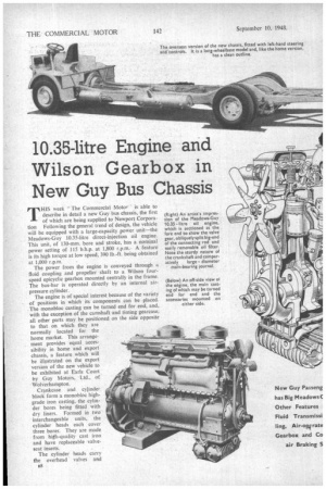
THIS week " The Commercial Motor ' is able to describe in detail a new Guy bus chassis, the first of which are being supplied to Newport Corporation Following the general trend of design, the vehicle will be equipped with a large-capacity power unit—the Meadows-Guy 10.35-litre direct-injection oil engine. This unit, of 130-mm. bore and stroke, has a nominal power setting of 115 bhp. at 1,800 r.p.m., A feature is its high torque at low speed, 390 lb.-ft. being obtained at 1,000 r.p.m.
The power from the engine is conveyed through a fluid coupling and propeller shaft to a Wilson fourspeed epicyclic gearbox mounted centrally in the frame. The bus-bar is operated directly by an internal airpressure cylinder.
The engine is of special interest because of the variety of positions in which its components can be placed. The monobloc casting can be turned end for end, and, with the exception of the camshaft and timing gearcase, all other parts may be positioned on the side opposite to that on which they are normally located for the home market. This arrangement provides equal accessibility in home and export chassis, a feature which will be illustrated on the export version of the new vehicle to be exhibited at Earls Court by Guy Motors, Ltd., of Wolverhampton.
Crankcase and cylinder block form a monobloc highgrade iron casting, the cylinder bores being fitted with dry liners. Formed in two interchangeable units, the cylinder heads each cover three bores. They are made from high-quality cast iron and have replaceable valve seat inserts. .
The cylinder heads carry the overhead valves and
a8 rocker gear All valves are made from heat-resistiirg steel. A masked inlet valve is used and is prevented from rotating by a slotted valve-spring collar and cotter pin, acting in conjunction with a hardened-steel tenon headed button positioned in the valve-rocker housing Decompression gear is provided.
Nitrided and of exceptionally robust construction, the crankshaft rotates in seven lead-bronze steel-backed pre cision-finish bearings Employing the same type of bearing, the connecting rods are split obliquely across the big-ends to facilitate withdrawal through the cylinder bores. The big-end caps are secured in position by four bolts, Toroidal-cavity aluminibm-alloy pistons are used. They have three compression and two scraper rings, one scraper ring being fitted above, and the second below, the fully floating gudgeon pin.
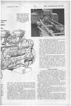
Driven through helical gearing at the flywheel end, the camshaft rotates in seven thin-shell pressure-fed precision-finish bearings, the valves being operated by cast•iron tappets and short push-rods Three auxiliary drive lines are provided on the near side of the engine, one above the other, and driven by a train of helical gears at the rear The exhauster is operated by the upper drive, and automatic advance and fuel pump by the centre drive The 12-volt or 24-volt dynamo is connected to the lower drive A C.A.V. fuel-injection pump is fitted, the speed being , controlled by a self-contained governor Automatic injection advance is taken care of by the centrifugally operated Meadows patent governor. Two oil-fuel filters are supplied, the primary filter being incorporated in the fuel-lift pump. and the secondary unit, a C.A.V fabric element, is located between the fuel-lift and injector pumps. C.A.V. four-spray long-stem injectors are fitted as standard
Full-flow Filtration
Lubrication of the engine is by force-feed A large-capacity gear-pattern oil pump is situated at
the rear of the engine and is driven by gears from the fuel-pump drive. Oil is drawn through a fully float. ing stiiiner and passed to a full-flow filter, consisting of four elements contained in a detachable chamber positioned at the forward end of the sump. Lubricant is supplied to the gudgeon-pin bush through a drilling in the 1-1 sectiQn of the connecting-rod assembly
Adequate engine cooling is assured by the 17-in sixbladed fan driven by an endless belt from the crankshaft pulley. Engine-water temperature is controlled by a bellows-pattern thermostat The power unit is supported in the chassis by a single-point bearing under the fan at the fore end, and by a mounting on each side of the flywheel housing at the rear Approximate weight of the engine, less oil and water, is given as 1.680 lb
Drive from the engine is taken through the fluid coupling, bolted directly to the flywheel, to the Wilson four-speed epicyclic gearbox, which provides ratios of 4,2, 2.37, 1.57 and 1 to 1 forward, and 6.09 to 1 reverse To lighten the controls, the gear-engaging pedal is con
nected through a control valve to an internal air-pressure cylinder operating the bus-bar of the gearbox.
Independent skew-gear drives are provided in the gearbox for the speedometer and the R.P automatic lubricator.
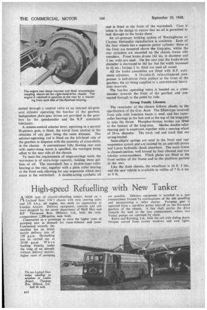
A remote-control selector lever, operating in a normal 14-pattern gate, is fitted, the travel from neutral in the selection of any gear being the same distance. The selector-operating rod is fitted on the left-hand side of the gearbox to dispense with the necessity of cross-shafts in the chassis. A conventional fully floating rear axle with under-slung worm is specified, the worrnpot being offset to the near side of the chassis.
To meet the requirements of stage-carriage work, the wormcase is of extra-large capacity, holding three gallons of oil. The wormshaft has a double-taper-roller bearing at the rear, together with a plain roller bearing at the front end, allowing for any expansion which may occur in the wormshaft. A double-acting synthetic oil seal is fitted at the front of the wormshaft. Care is taken in the design to ensure that no oil is permitted to leak through to the brake shoes.
An air-pressure braking system of Westinghouse or Clayton Dewandre manufacture is available, Each of the four wheels has a separate power cylinder; those at the front are mounted above the king-pins, whilst the rear cylinders are mounted on the chassis frame side members. Front brake drums 16-11 ins, in diameter and 4 ins, wide are used. On the rear axle the brake-drum diameter is decreased to 16+ ins but the width increased to 61 ins.; facings in. thick are used all round.
All the brake assemblies are fitted with R.P. auto
matic adjusters. A 10-cubic-ft. twin-cylindered compressor is belt-driven from pulleys at the front of the gearbox, the air being supplied to a conventional heavyduty reservoir.
The bus-bar operating valve is located on a crossmember towards the front of the gearbox and connected through to the pedal by rods
Strong Family Likeness
The remainder of the chassis follows closely to the specification of the Guy Arab The Elliot-type reversed front axle with 1-section beam is used, and has taperroller bearings in the hub and at the top of the king-pins to take the thrust. Phosphor-bronze bushes are fitted
at the bottom of the king-pins. Marles double-roller steering gear is employed, together with a steering wheel of 20-in, diameter. The track rod and track link are spring-loaded.
Semi-elliptic springs are used in the front and rear suspension system and are assisted by an anti-roll device and Luvax hydraulic shock absorbers, The main frame is channel-section, well braced by four channel and two tubular cross-members. Flitch plates are fitted to the front section of the frame and in the platform portion at the rear.
Like the Arab chassis, the wheelbase is 16 ft. 3 ins., and the new vehicle is available in widths of 7 ft. 6 ins. or 8 ft.