


Rubber-bushed Auxiliary Suspension System
Page 36
If you've noticed an error in this article please click here to report it so we can fix it.
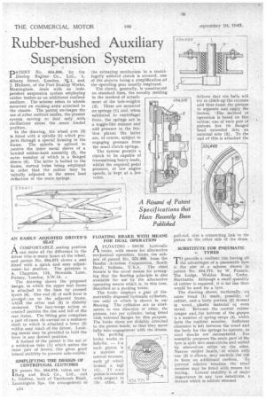
PATENT No. 554,695, by the Dunlop Rupber. Co., Ltd., 1, Albany Street, 'London, MO, and J. Hickson, of the Fort Dunlop Works, Birmingham, deals with an independent suspension sysiern employing rubber bushes as an additional resilient medium. The scheme refers to wheels mounted on rocking arms attached to the chassis. The patent envisages the use of other resilient means, the present system serving to deal only with oscillations about the _mean loaded position.
In the drawing, the wheel arm (9) is fitted with a spindle (1) which projects through a special housing in the frame. The spindle is splined to receive the inner metal sleeve of a bonded rubber-bush assembly (2), the outer member of which is a flanged sleeve (4). The latter is bolted to the frame, slotted holes being employed in order that the rubber may be initially adjusted to the mean load deflection of the main springs.
AN EASILY ADJUSTED DRIVER'S SEAT
A COMFORTABLE. seating position ti can Make all -the difference to the driver who is many hours at the wheel, and patent No. 554,671 shows a seat fitted with a quick and easy adjustmentfor position. The patentee is A. Chapman, 115, Howards Lane, Putney, London, S.W.15, The drawing shows the proposed design, in which the upper seat frame is attached to the • base by crossed levers (6). One end (3) of each lever is pivotedon to the adjacent frame, what the other end (5) is slidably mounted. The lazy-tongs action so created permits the rise and fall of the seat frame. The lifting gear comprises a pair of cams (4) carried on a common shaft to which is attached a lever (2) within easy reach of the driver. Locking means may be provided to hold the lever in any desired position.
A feature of the patent is the use of a; welded-on tube (1) which unites the inner pair of levers; this gives good lateral stability to prevent side-wobble: SIMPLIFYING THE DESIGN OF CENTRIFUGAL CLUTCHES I N patent No. 554,576, taken out by Borg and Beck Co., Ltd., and L. GOdfrey, both of Tachbrook Road, Leamington Spa, the arrangement of A34 the actuating mechanism in a centrifugally assisted clutch is covered, one of the objects being a simplification of the operating gear usually employed.
The clutch, generally, is constructed on standard lines, the novelty residing in the methodof attachment of the bob-weights (2). These are mounted on springs (1) and, when subjected to centrifugal force, the springs act in a toggle-like manner and add pressure to the friction plates; the, latter are, of course, subject to engaging pressure from the usual clutch springs.
The System permits a clutch to be capable of transmitting heavy loads, whilst the required pedal pressure, at low engine speeds, is. kept at a low value.
FLOATING BRAKE WITH MEANS FOR' DUAL OPERATION
A FLOATING SHOE hydraulic brake, with means for alternative mecpanical operation, forms, the subject of patent No. 551,466, from the Bendix .Aviation Corporation, South Bend, Indiana, U.S.A. • The chief feature is the novel means for arranging that the floating principle is also available for use by the alternative operating means which is, in this case, described as a parking brake. . The brake employs a _pair of diametrically disposed hydraulic cylinders, one only of which is shown in our drawing. The cylinders act as abutments in one direction or other, the pistons, two per cylinder, being fitted with external flanges -for this purpose. The brake shoes are slidably attached to the piston heads, so that they move fully into engagement with the drums.
The parking brake works as — I n
each piston is 4 a number of conical recesses, each ,of which hOu-ses a. ball
( I). If one piston is. rotated with .respect to the other, it • follows that the balls will try to climb up the recesses and thus cause the pistons to separate and apply the brakes. "-The method of operation is based on this. action; one of each pair of pistons has its flanged head extended into an external arm (2). To the • end of this is attached the pull-rod, also a connecting link to the piston on the, other side Of the drum
SUBSTITUTE FOR PNEUMATIC 4, TYRES Toprovide a resilient rim having all the advantages of a pneumatic tyre is the aim of a scheme shown in patent No. 554,771, by W. Francis, The Lodge, Weldon Road, Corby, Northants. Although a small quantity of rubber is required, it is far less than would be used for a 'tyre.
The drawing shows, sectionally,' an outer tread (1) made, possibly, of rubber, and a body portion (2) formed in wood, ...plastic material or even metal. 'Between the central rubber tongue and, the bottom of the grpqve is a number of spring strips (4), which form the resilient member. Sufficient clearance is left between the tread and the body for the springs to operate, as road shocks are encountered. For assembly purposes_the main part of the tyre is split into semi-circles and united by screwed-on strips on the sides. Narrow rubber bands," of which only one (3) is sliown, may encircle the rim • to form an, additional cushion. To prevent relative rotation the tread member may be fitted with means for keying. Lateral stability is of major importance in any tyre substitute, a feature which is seldom-stressed