


A Rotary Distributor Injection Pump
Page 68
If you've noticed an error in this article please click here to report it so we can fix it.
A COMPREHENSIVE patent, No.
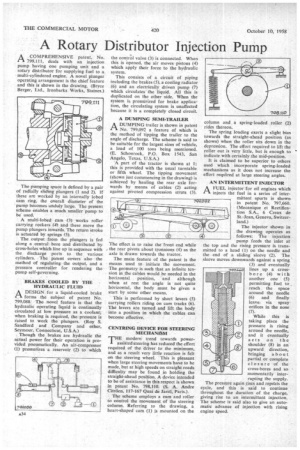
799,111, deals with an injection pump having one pumping unit and a rotary distributor for supplying fuel to a multi-cylindered engine. A novel plunger operating arrangement is the chief feature and this is shown in the drawing. (Bryce Berger, Ltd., lronbarks Works, Staines.) The pumping space is defined by a pair of radially sliding plungers (1 and 2). If these are worked by an internally lobed cam ring, the overall diameter of the pump becomes unduly large. The present scheme enables a much smaller pump to be used.
A multi-lobed cam (3) works roller carrying rockers (4) and these move the pump plungers inwards. The return stroke is actuated by springs (5).
The output from the plungers is fed along a central-. bore and distributed by. cross-holes which line up in sequence with the discharge ports to the various cylinders. The patent covers also the method of regulating the output, and a pressure controller for rendering the pump self-governing.
BRAKES COOLED BY THE HYDRAULIC FLUID
A DESIGN for a liquid-cooled brake 1-1 forms the subject of patent No. 799,088: The novel feature is that the hydraulic operating liquid is continually circulated at low pressure as a coolant; when braking is required, the pressure is raised to -work the plungers. (Roy S. Sandford and Company and other, Seymour, Connecticut, U.S.A.)
Though the brakes are hydraulic the actual power for their operation is provided pneumatically. An air-compressor (1) pressurizes a reservoir (2) to which the control valve (3) is connected. When this is opened, the air moves pistons (4) which apply their force to the hydraulic system.
This consists of a circuit of piping including the brakes (5), a cooling radiator (6) and an electrically driven pump (7) which circulates the liquid. All this is duplicated on the other side. When the system is pressurized for brake application, the circulating system is unaffected because it is a completely closed circuit.
A DUMPING SEMI-TRAILER
ADUMPING trailer is shown in patent No. 799,092 a feature of which is the method of tipping the trailer to the angle of discharge. The scheme is said to be suitable for the largest sizes of vehicle, a load of 100 tons being mentioned. (E. Schonrock, P.O. Box 1543, San Angelo, Texas, U.S.A.)
'A part of the tractor is shown at 1; this is provided with the usual turntable or fifth wheel. The tipping movement (shown just commencing in the drawing) is achieved by hauling the rear axle forwards by means of cables (2) acting against pivoted compression struts (3), The effect is to raise the front end while the rear pivots about trunnions (4) as the axle is drawn towards the tractor.
The main feature of the patent is the means used to initiate the movement. The geometry is such that an infinite tension in the cables would be needed in the horizontal position, and although when at rest the angle is not quite horizontal, the body must be given a start by some other means.
This is performed by short levers (5) carrying rollers riding on cam tracks (6). The levers are turned and lift the body into a position in which the cables can become effective.
CENTRING DEVICE FOR STEERING MECHANISM
THE modern trend towards power' assisted steering has reduced the effort required of the driver to the minimum, and as a result very little reaction is felt on the steering wheel. This is pleasant when large steering movements have to be made, but at high speeds on straight roads difficulty may be found in holding the straight-ahead position. A device intended to be of assistance in this respect is shown in patent No. 798,110. (S. A. Andre Citroen, 117-167 Quai de Javel, Paris.).
The scheme employs a cam and roller to control the movement of the steering column. Referring to the drawing, a heart-shaped cam (1) is mounted on the column and a spring-loaded roller (2) rides thereon.
The spring loading exerts a slight bias towards the straight-ahead position (as shown) when the roller sits down in the depression. The effort required to lift the roller out is very little, but is enough to indicate with certainly the mid-position.
It is claimed to be superior to others used which incorporate spring-loaded mechanisms as it does not increase the effort required at large steering angles.
AN INTERMITTENT INJECTOR
AFUEL injector for oil engines which injects the fuel in a series of intermittent spurts is shown in patent No. 797,660. (Mecanique et Rectification S.A., 6 Creax de St.-Jean, Geneva, Switzerland.)
The injector shown in the drawing operates as follows: The injection pump feeds the inlet at the top and the rising pressure is transmitted to a head (1) on the needle and the end of a sliding' sleeve (2). The sleeve moves downwards against a spring (3) and eventually lines up a crossbore (4) with another one (5) permitting fuel to reach the space around the needle (6) and finally leave, via spray. orifices in the nose (7).
While this is taking place the pressure is rising around the needle, and it eventually acts on the shoulder (8) in an upward direction, bringing about partial or complete closure of the cross-bores and so momentarily interrupting the supply.
The pressure again rises and repeats the cycle, and this is said to continue throughout the duration of the charge, giving rise to an intermittent injection. The scheme is said also to give an automatic advance of injection with rising engine speed.