New Method of Driving Sleeve Valves
Page 36

If you've noticed an error in this article please click here to report it so we can fix it.
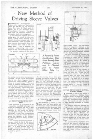
1NTERESTING developments i sleeve-valve engines are disclosed in patent No. 564,083, by the Standard Motor Co., Ltd., J. Black and .W. Turner, all of the Standard Motor Works, Canley, Coventry. The patent dealt with an improved method of driving the single sleeve employed.
At one end of the engine is the usual timing gear (1), which, in this case. drives a small rotary member (2) in which is bored an eccentric hole. The hole surrounds a stub (3) which projects from the sleeve and is fitted into the eccentric hole with a ball-andsocket joint. Thus is imparted the combined reciprocating and rotary motion in the well-understood manner.
The novelty consists of the means
for passing on the drive to snecessive cylinders, 'A stub (4) on ,the opposite sidei of the sleeve engages another eccentrically bored member, which it drives in a rotary sense. The next sleeve is similarly ball-jointed on its stub (5) into a second eccentric bore, the whole forming a kind of two-throw crankshaft connecting the two. sIeeVes. Although the angular distance of the two bores is shown as 100 degrees, this is purely for the sake or clarity, 90 degrees being the actual angle. Balance weights on the rotary members also form part of the patent,
AN IMPROVED MANIFOLD HOT SPOT
THE provision of a hot-spot in the induction manifold, although very helpful in vaporizing the fuel, is also inclined to reduce the volumetric efficiency of the engine by unduly expanding the charge. To obtain the advantage without this corresponding defeat is the aim of a scheme shown in patent No. 563,895, by H. Weslake, 25, Westleigh Avenue, Putney, London,
This inventor proposes to provide a hat-spot which is out of the path of the mixture, but which can be reached by any small droplets of unvaporized fuel. It is most suitable for down. draught carburetters in which the action, as will he appreciated, can be assisted by gravity.
In the drawing, 1 is a brass plate dividing the exhaust system (2) from the induction passage (3). From the inlet (4) the incoming mixture is divided by a deflector (5) and passes to right and left without meeting the hot plate (1), an action which is helped by the presence of a wall(6). But any droplets of fuel, by virtue -of their greater momentum, reach the bottom wall and pass through perforations. therein to reach the hot plate. Here• theyare vaporized and immediately returned into the main mixture stream.
A TWO-RATIO HAND-BRAKE LEVER •
AMECHANISM by which. a hand-brake lever can first lightly pull the shoes into contact and then-apply an increased force for the actual braking is shown in patent No. 564,096, by C. White and Comrner Cars, Ltd.,
• Bisect Road, Luton. The mechanisni affords u temporary fulcrum to the lever for the initial high-speed movement and then changes over to a second fulcrum to provide increased leverage for the final powerful pull.
The lever is pivoted on a hollow pin (1) carried in a bracket (2), which itself is pivoted on a fixed pin (3). Bracket 2 is extended under the pivot to form the retaining ratchet (4), which is engaged by the• usual releasable pawl. The hollow pivot (1) is temporarily locked to a stationary bracket (5) by means of a spring-loaded ball (6), which is pressed into a recess.
When the lever is first moved, it pivdts on pin 1 and applies the long. range but light pull. When the pull is increased, however, the ball 6. is unseated and the lever then moves about pin 3, thus giving an increased leverage. The brake rod is, of course, attached to the lowermost end of the lever. The ratchet-and-pawl mechanism does not operate on the secondary Motion, and if a " stay-on" brake be "required, a second ratchet must be fitted.
DETAIL IMPROVEMENT IN WELLKNOWN BRAKE
AMODIFICATION in the design at . the well-known Girling brake forms the subject of patent No. 563,969.. which comes from J. Pratt, Guildhall Buildings, Navigation Street, Birmingham. The object is to allow the shoes a slight floating movement in a radial direction, The drawingshows the fulcrum end , of a pair of shoes which can be adjusted by a spreading mechanism in the boss (1). The spreader pushes on plungers (2), which are slotted to receive the webs of the shoes, Ilithertd, the bottom of the slot has been given a convex outline to co-operate with the curved surfaces (3) of the webs; this gave' a definitelocation to the brake. shoes. "
The present scheme employs a loon piece (4). flat where it Meets the slotbottom and curved to suit the shoe. The flat surface permits the shoes to float slightly and thus settle•themselves into the drum without undesirable constraint.


