 1
1 2
2 3
3 4
4 5
5 6
6 7
7 8
8 9
9 10
10 11
11 12
12 13
13 14
14 15
15 16
16 17
17 18
18 19
19 20
20 21
21 22
22 23
23 24
24 25
25 26
26 27
27 28
28 29
29 30
30 31
31 32
32 33
33 34
34 35
35 36
36 37
37 38
38 39
39 40
40 41
41 42
42 43
43 44
44 45
45 46
46 47
47 48
48 49
49 50
50 51
51 52
52 53
53 54
54 55
55 56
56 57
57 58
58 59
59 60
60 61
61 62
62 63
63 64
64 65
65 66
66 67
67 68
68 69
69 70
70 71
71 72
72 73
73 74
74 75
75 76
76 77
77 78
78 79
79 80
80 81
81 82
82 83
83 84
84 85
85 86
86 87
87 88
88 89
89 90
90 91
91 92
92 93
93 94
94 95
95 96
96 97
97 98
98 99
99 100
100 101
101 102
102 103
103 104
104 105
105 106
106 107
107 108
108 109
109 110
110 111
111 112
112 113
113 114
114 115
115 116
116 117
117 118
118 119
119 120
120 121
121 122
122 123
123 124
124 125
125 126
126 127
127 128
128 129
129 130
130 131
131 132
132 133
133 134
134 135
135 136
136 137
137 138
138 139
139 140
140 141
141 142
142 143
143 144
144 COLLECTIVE EXHIBIT
Page 41
Page 42
Page 43
If you've noticed an error in this article please click here to report it so we can fix it.
give ample proof of its growing popularity. From read tests which have been carried out during the past few months by The Commercial Motor staff we can personally support the claims of manufacturers that oil engines are, in their present stage, quite suitable for use in roadtransport vehicles.
From the point of view of progressive design, therefore, one would be tempted to give pride of place to the compression-ignition engine as applied to moderate and largesized vehicles. On the other hand, sight should not be lost of the great advances made in control, springing and in silence of operation.
Having generalized, we can go more fully into the subject of advancement in design. No trouble in the shape of frame distortion should now be experienced by operators of large passenger and goods vehicles, for the deep sections of the side members and the manner in which they (the main channels) are braced together seem to indicate that the experience gained with the prototypes of the latest chassis has been fully utilized.
The Dennis 12-tonuer with its three-way hydraulic tipping gear is of particularly sturdy construction, all possi bility of the frame lozenging or weaving being eliminated, by including a number of well-ditched cross-members at all vulnerable points. Then, in the case of the Thornyereft 6-ton chassis, and, indeed, the double-deck-bus chassis, the simplicity of the lines of the framework generally is well worthy of comment and gives an impression of trimness which is to be desired.
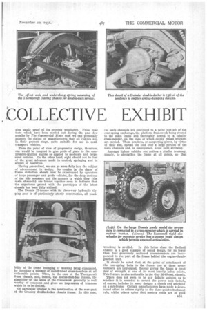
Of particular interest is the construction of the rear part of the Crossley double-decker chassis frame. In this case, the main channels are continued to a point just aft of the rear-spring anchorage, the platform framework being riveted to the main frame and thoroughly braced by a tubular cross-member, on the ends of which deeply ribbed brackets are carried. These brackets, or supporting pieces, by virtue of their size, spread the load over a large portion of the main channels and, in consequence, avoid local stressing.
Amongst lighter vehicles one notices a similar tendency, namely, to strengthen the frame at all points, so, that
wracking is avoided. In this latter class the Bedford chassis is a good example of sound design, for no fewer than four generously sectioned cross-members are incorporated in the part of the frame behind the engine-clutchgearbox unit.
It should be noted that at the point of attachment of the rear-spring bolts to the frame two of these crossmembers are introduced, thereby giving the frame a great deal of strength at one of its most heavily laden points. This feature is also noticeable in the Guy 30-40-cwt. chassis.
There does not seem to be any definite opinion as to whether it is essential to mount the power unit (which, of course, includes in many designs a clutch and gearbox) on a sub-frame. Certain manufacturers have made a determined effort to adhere rigidly to the three-point-attachment rule, whilst others opine that modern roads are so good as to make such precautions unnecessary in any vehicle which is not intended for use on cross-country work.
The Crossley double-decker certainly comes into the former class, for the engine is mounted in one sub-frame and the gearbox in another ; both have a three-point attachment to the frame cross-members, and in each case the trunnion mounting is located forward.
The question of suspension now claims attention, for it is closely allied to frame design. For four-wheeled vehicles, semi-elliptic springs are, of course, universally employed; they fit in nicely with the general scheme of things ana provide good axle location.
It is interesting to note that, in some cases, frames have been widened at the rear in order to bring the spring location of the axle as near as possible to the track of the wheels, whilst, in others, the simplicity of straight lines in the general build of the chassis has been considered important and outrigger brackets have been arranged to bring the springs close up to the wheels.
This arrangement is quite satisfactory and serves exactly the same purpose as increasing the width of the frame itself. It is, of course, unnecessary to state that the reason that this wide "spring base" is desirable is because the overturning couple, when cornering, is reduced. Turning now to a consideration of power units, in general specification there is little alteration to record in the well-known types, and it is only when a detailed examination of the various engines shown is undertaken that one realizes what has been done during the past year or so. Careful attention has been paid to lubrication matters, for in nearly all the large power units sensible oil filters, and, in certain cases, coolers as well, have been incorporated.
The Daimler system of cooling the lubricant is retained in the 1932 models, whilst in the new Thornycroft doublesleeker chassis a finned cast-aluminium cooler is embodied and is placed in the air stream of the fan ; in addition, there is an Auto-Klean filter which is constantly cleared of obstruction by connecting the movable member of the gilled filter, to the clutch pedal. D52 For passenger work, on coaches and buses, the generally accepted practice is to use a six-cylindered engine developing from 90 b:h.p. to 130 b.h.p., and in every case the crankcase cylinder-block arrangements are built on particularly stiff lines in order to provide a rigid structure in which to mount the crankshaft.
Seven bearings are universally employed for the lastnamed component and a full-pressure lubrication system is invariably used. In the Daimler sleeve and poppet-valve engines, a special "bleed "-hole is drilled in the connecting rod big-end journals to provide a stream of oil for cylinder lubrication when the engine is first started up from cold.
This question of cylinder lubrication is one which might, with advantage, receive more attention from designers, for with present-day piston-cylinder tolerances and tight-fitting journal bearings for the crankshaft, little lubricant escapes to be flung on to the cylinder walls when the engine and oil are cold. Consequently, wear must take place at a rapid rate during this warming-up process.
In the matter of valve layout there is no concerted opinion, for all types of disposition are shown. The sidevalve school of thought maintains that the simplicity permitted by the direct application of the cams to the valve tappets, combined with an overall improvement in efficiency which has recently been made possible by compacting the combustion-chamber spaces, renders the type inherently better than overhead-valve engines with their attendant push-rods and rocker gear.
Certain manufacturers have made efforts to evolve what really might be termed a "side-by-side overhead-valve layout," the Morris-Commercial Dictator engine, for example, having side-hy-side valves incorporated in almost hemispherical combustion chambers and operated by rockers from a camshaft lying immediately below the cylinder-head joint.
There are no pusherode and the camshaft, timing, etc., are undisturbed when the cylinder heads are removed for decarbonizing and valve-grinding purposes. Of somewhat shutJar layout is the Guy valve gear, hut, in this case, U13.1491'2 stems are inclined downwards.
Carburation on six-cylindered engines has always been a. .difficult matter and one which calls for experimental or trial-and-error methods to be employed in order to obtain the best results. .Small differences in shape, and the disposition of carburetters, inlet manifolds, etc., can be seen, and these can be interpreted only as being attempts to improve thermal efficiency, slow running and maximum power.
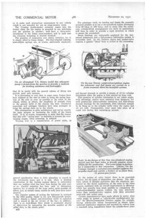
Compression-ignition engines are represented by Gardner four-cylindered units fitted to T.S. chassis, and a Dennis 12-tanner employing a six-cylindered engine of the maker's own design. With bore and stroke dimensions of 110 mm. and 140 mm., the latter engine develops 92 b.h.p. to 95 b.h.p. at 2,000 r.p.m. and possesses a good torque figure at low and medium revolution speeds, Of particularly massive constsuction' the cylinders are formed in pairs and are attached by substantial bolts to a deep aluminium crankcase. There are two auxiliary lines, one comprising an exhauster pump and the usual Bosch fuel pump with its combined governor, whilst the other comprises the dynamo and the water pump with an A.C. fuel pump incorporated in the housing which contains the auxiliary line of shaft at the rear of the engine.
The Gardner engine, of course, needs no introduction, for in four, five or six-cylindered types it has been incorporated in many goods and passenger vehicles, and has proved itself to be _reliable and economical.
In considering transmission systems, it would be difficult not to place the Daimler layout in the forefront, because of its unorthodox nature. The Fluid Flywheel with its slipping-clutch characteristic at low rates of engine-revolution speeds is retained, likewise the four-speed, pre-selective gearbox. Many Daimler vehicles are in service with this transmission system and we learn that they have given entire satisfaction even under particularly arduous service conditions.
It should be remembered that the Fluid Flywheel does not act like a free wheel in any shape or form, but causes a torque reaction to be built up, bearing some relation to engine-revolution speed and which, we understand, reaches the remarkable efficiency of 97 per cent at the most favourable point in the efficiency curve. • Any criticism regarding " slip " can, therefore, be discounted.
For the rest, the normal layout of a single-plate clutch, a four-speed gearbox and the usual tubular propeller-shaft conveying the drive to a worm-driven rear axle seems to be universally employed.
Gearboxee are certainly quieter in operation than they used to be, this desirable characteristic being attributable to a combination of a number of improvements incorporated in the .general layout. First and foremost is the fact that
the teeth of the pinions • are now always ground, whilst both main and secondary shafts have, in a number of cases, been stiffened up, besides being mounted at three points ,(a centre bearing being introduced).
There is no Unanimity of opinion as to whether the gearbox should be mounted unitwise with the engine or separately; this matter really seems to resolve itself into a question of convenience.
There is another aspect' of the ease. To the separately mounted arrangement a short clutch shaft is, of course, essential, and if the universal joints on this shaft be of the fabric type, a certain amount of vibration and reverberation due to slight torsional oscillations of the crankshaft are prevented from building up in the propeller shaft.
There is little possibility of trouble occurring in the fabric joints, because the shaft does not articulate. Long propeller shafts are, of course, avoided, because at present-day engine and road speeds, "flinging," with consequent vibration, is an ever-present bogy if certain pre-determined lengths of unsupported shaft be exceeded.
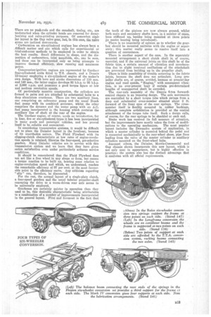
The rear-axle assembly of the Dennis 6-ton forwardcontrol chassis is an imposing design. The axle movements are controlled by a short torque tube which swings from a deep and substantial cross-member situated about 2 ft. forward of the front eyes of the rear springs. The crossmember itself is flexibly mounted in rubber bushings, although complete artieblation is provided at the central attachment of the torque tube itself. such a design calls, of course, for the rear springs to be shackled at each end.
Brake work has received its full measure of attention, but the improvements have moetly taken the form of modifications to the operating mechanism. The most popular layout includes the Dewandre system of application, in which a master cylinder is mounted behind the pedal and is connected mechanically to the rear-wheel shoes, pipe lines leading from the valve of the master cylinder to auxiliary cylinders mounted on the front-wheel hubs.
Amongst others, the Daimler, Morris-Commercial and Guy chassis shown incorporate this new layout, which is not only neat in appearance, but is highly effective in practice ; the system also has the distinct advantage that it conforms with all official requirements.