 1
1 2
2 3
3 4
4 5
5 6
6 7
7 8
8 9
9 10
10 11
11 12
12 13
13 14
14 15
15 16
16 17
17 18
18 19
19 20
20 21
21 22
22 23
23 24
24 25
25 26
26 27
27 28
28 29
29 30
30 31
31 32
32 33
33 34
34 35
35 36
36 37
37 38
38 39
39 40
40 41
41 42
42 43
43 44
44 45
45 46
46 47
47 48
48 49
49 50
50 51
51 52
52 53
53 54
54 55
55 56
56 57
57 58
58 59
59 60
60 61
61 62
62 63
63 64
64 65
65 66
66 67
67 68
68 69
69 70
70 71
71 72
72 73
73 74
74 75
75 76
76 77
77 78
78 79
79 80
80 81
81 82
82 83
83 84
84 85
85 86
86 87
87 88
88 89
89 90
90 91
91 92
92 93
93 94
94 95
95 96
96 97
97 98
98 99
99 100
100 101
101 102
102 103
103 104
104 105
105 106
106 107
107 108
108 109
109 110
110 111
111 112
112 113
113 114
114 115
115 116
116 117
117 118
118 119
119 120
120 121
121 122
122 123
123 124
124 125
125 126
126 127
127 128
128 129
129 130
130 131
131 132
132 133
133 134
134 135
135 136
136 137
137 138
138 139
139 140
140 141
141 142
142 143
143 144
144 145
145 146
146 147
147 148
148 149
149 150
150 151
151 152
152 153
153 154
154 155
155 156
156 157
157 158
158 159
159 160
160 161
161 162
162 163
163 164
164 165
165 166
166 167
167 168
168 169
169 170
170 171
171 172
172 A SAFETY TANKER OF THE FUTURE
Page 40
Page 41
Page 42
Page 47
Page 48
Page 49
If you've noticed an error in this article please click here to report it so we can fix it.
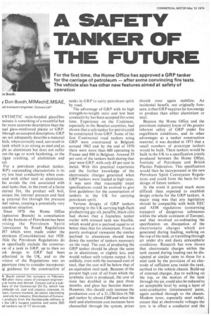
For the first time, the Home Office has approved a GRP tanker for the carriage of petroleum — after some convincing fire tests. The vehicle also has other new features aimed at safety of operation y Don Booth,MIMechE,MSAE,
lief transport engineer, Conoco Ltd*
YNTHETIC resin-bonded glassfibre minate is something of a mouthful but far more accurate description than the ;ual glass-reinforced plastic or GRP. it hough an accepted description, GRP )es not adequately describe a material hich, when correctly used, can result in tank which is as strong as steel and as ;ht as aluminium but does not suffer om the age or work hardening, or the tigue cracking, of aluminium and eel.
For a petroleum product tanker, RP's outstanding characteristic is its !..ry low heat conductivity when cornired with either steel or aluminium. his avoids the risk associated with ietal tanks that, in the event of a fierce cternal fire, the product will boil, crease the internal pressure and feed le external fire through the pressure :lief valves, creating a potentially very azardous situation.
Since 1970 the Home Office Explosives Branch) in consultation ith the Institute of Petroleum has been !vising the Petroleum Spirit L'onveyance by Road) Regulations )57 which were made under the etroleum (Consolidation) Act 1928. (hile the Petroleum Regulations do ot specifically exclude the construeon of a tank in GRP, up to then no ink design in GRP had been uthorized in the UK, and so the vision of the Regulations was an pportune time to consider incorporatig guidance for the construction of tanks in GRP to carry petroleum spirit by road. The advantage of GRP with its high strength-to-weight ratio and low heat conductivity has been accepted for some time. Experience On the Continent, especially in the Benelux countries, had shown that a safe tanker for petrol could be constructed from GRP. Some of the first Continental road tankers using GRP were constructed in Belgium around 1962 and by the end of 1970 there were more than 600 operating in France and 800 in Belgium. Around 55 per cent of the tankers built during that year were GRP, with only 45 per cent in metal. With this practical experience and the further knowledge of the electrostatic charges generated when GRP tankers were loaded at high rates, .it was seen that reasonably exact specifications could be evolved to give firm guidelines for the construction of tankers in the UK for carrying petroleum spirit.
Various designs of GRP tankers operating in the UK carrying high-flash products (eg gas oil, paraffin, black oils) had shown that a frameless tanker trailer with stressed tank was feasible, which would give a payload equal to or better than that for aluminium. From a purely ecological viewpoint the similar payload to aluminium should keep down the number of tankers necessary on the road. The cost of producing the GRP tanker should be about the same as in aluminium, or slightly less, and would reduce with volume output. It is unlikely, even with the increased cost of steel, that the cost will be below that of an equivalent steel tank. Because of the present high cost of oil from which the synthetic resin is produced, the cost of resin has doubled in the past three months, and glass has become dearer. However, this should only increase the production cost of a 21,150-litre (4,700 gal) tanker by about £300 and when the steel and aluminium cost increases have channelled through the system, prices should once again stabilize. An incidental benefit, not originally foreseen, is that GR P requires far less energy to produce than either aluminium or steel.
Because the Home Office and the petroleum industry know of the greater inherent safety of GRP under fire engulfment conditions, and its other advantages as a tanker construction material, it was decided in 1971 that a small numbers of prototype tankers would be built. These tankers would be built in the UK to a specification jointly produced between the Home Office, Institute of Petroleum and British Plastics Federation. This specification would then be incorporated in the new Petroleum Spirit Conveyance Regulations and could form the basis for the design of future tankers.
In the event it proved much more difficult than expected to establish design criteria for the GRP tankers. A major snag was that any legislation should be compatible with both EEC and ADR regulations (concerning transport of dangerous substances within the whole continent of Europe), and that involved co-ordinating the specification on dissipation of the electrostatic charges which are generated during loading, walking on the top of the tank, or travelling through air under dry and dusty atmospheric conditions. Research has now shown that electrostatic charges within the tank caused during loading can be dissipated at similar rates to those for a steel tank by the provision of an electrode of sufficient area inside the tank, earthed to the vehicle chassis. Build-up of external charges, due to walking on the top, or the motion of the tank through the air, could also be reduced to an acceptable level by using a layer of semi-conductive (intumescent) paint, again earthed through to the chassis. Modern tyres, especially steel radial, ensure that at electrostatic voltages the tyre is in effect a conductor and the vehicle is earthed to ground through the tyres.
However, notwithstanding all the work that had been done on GRP there was a lack of practical knowledge about what would happen to a GRP tank containing either liquid or petroleum spirit vapour, subjected to an external fire. The Home Office therefore arranged with the Fire Service Technical College at Moreton-in-Marsh to subject one ;teel, one aluminium, and one GRP tanker to external flame to ascertain what the effect would be.
What the tests showed
The experiments were carried out on :,-ebruary 22 1973 with results which :ompletely justified the beliefs of both he Home Office and the petroleum ndustry that a GRP tank was the safest n fire conditions. The separate tests vere conducted with steel, aluminium ind GRP 4,545-litre (1,000 gal) tanks .ontaining 3,405 litres (750 gal) of mphtha, mounted over steel trays conaining 682 litres (150 gal) of naphtha, vhich was ignited. Naphtha was chosen )ecause it has approximately the same tharacteristics as petrol but does not :arry such a high excise duty.
The tests on both the aluminium and teel tanks had to be terminated after ■ etween five and five and a half minutes oecause the fire was rapidly approachrig an uncontrollable condition, as the iaphtha inside was boiling and feeding he external flame. It was also probable hat the vapour pressure inside was ncreasing faster than the emergency ent valves could dissipate it. The GRP ank experiment was abandoned after bout 14 minutes because after 10 ainutes the external fire had consumed the 682 litres (150 gal) from the bottom tray without increasing the temperature inside the tank to a sufficient level to cause the fire to be fed from inside. There was some exterior scorching of the tank which caused a slight delamination of the GRP, but not enough to cause the tank to lose its integrity. One of the side bottom supports (which was not in contact internally with the tank liquid) collapsed, allowing the tank to slump down on that side, but again the tank maintained its integrity. The amount of the contents of the tank consumed in the fire was not measurable.
On the top of the aluminium tank, a section about 1.07 m (3ft 6in) long by 0.46 m (I ft 6in) wide, not in contact with the naphtha, melted and allowed the pressure within the tank to reduce to only slightly above atmospheric; about 682 litres (150 gal) of naphtha, were consumed from inside the tank. The steel tank remained complete although 1,227 litres (270 gal) of naphtha were ejected through the vent valves to feed the external fire.
The results of this test proved most conclusively that a GRP tank was far safer in these conditions than either steel or aluminium.
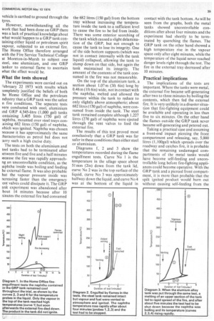
Diagrams 1, 2 and 3 show the temperatures recorded during the flame engulfment tests. Curve No 1 is the temperature in the ullage space about 51 mm (2in) down from the tank lid, curve No 2 was in the top surface of the liquid, curve No 3 was approximately halfway down the liquid, and curve No 4 was at the bottom of the liquid in contact with the tank bottom. As will be seen from the graphs, both the metal tanks showed uncontrollable conditions after about four minutes and the experiment had shortly to be terminated by quenching the flames. The GRP tank on the other hand showed a high temperature rise in the vapour space only after eight minutes, while the temperature of the liquid never reached danger levels right through the test. The fire in the external tray decreased after 10 minutes.
Practical implications
The implications of the tests are important. Where the tanks were metal, the external fire became self-generating after two to three minutes by boiling the contents, which then fed the external fire. It is very unlikely in a disaster situation that fire-fighting equipment could be available and operating in less than five to six minutes. On the other hand the flames outside the GRP tank never became self-generating and petered out.
Taking a practical case and assuming a front-end impact piercing the front compartment and releasing, say, 5,000 litres (1,100gal) which spreads over the roadway and catches fire, it is probable that the remaining undamaged compartments of the metal tanks would have become self-feeding and uncontrollable long before fire-fighting appliances could become operative. With the GRP tank and a pierced front compartment, it is more than probable that the spilt ignited product would burn out without causing self-feeding from the undamaged compartments.
A further interesting side result from the test was that it enabled the latest pattern of EMCO F337 455mm top cover lid to be tested under fire and pressure conditions.
This lid was developed to include all the recommendations from the Home Office and the Institute of Petroleum Technical Committee on maximum venting in an emergency, and security of locking. In all the tests the EMCO lid performed well and matched the claims made by EMCO-Wheaton. It is interesting to observe that on the steel tank where the tank and top lid maintained their integrity, it is probable that the internal pressure forced so much product through the lid that this product kept the lid from melting. On the aluminium tank where the top section of tank melted allowing the internal pressure to reduce, there was only a small amount of product forced through the lid and parts of it melted. With the GRP tank, without the high internal temperature and assumed pressure rise, there was no induced cooling and the lid melted. This, however, prevented any tendency for the internal pressure to rise and only slight initial pressure venting was evident.
Apart from.the specific reason for the test at Moreton-in-Marsh, the physical testing of all three tanks under actual fire conditions enabled an objective assessment to be made of what actually happens to tanks with low flash products, when subjected to external flame impingement. Although theoretically one knows and can calculate what will happen, the short time actually available to extinguish a fire, before the heat is sufficient to cause the product inside to feed the internal flame, does accentuate the need for adequate and correctly applied initial fire extinguishing. One lesson learned was that even high flash products such as gas oil could be a potential hazard without adequate emergency venting of the top cover lid and that the standard practice of using single vented top cover lids on bulk tanks for low flash products could be potentially dangerous. Very few of Conoco's tankers were actually to this design, but all have now been changed after the Moreton-in-Marsh experiment.
The prototype
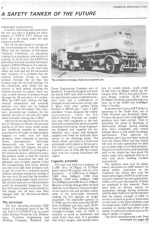
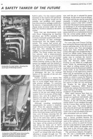
The first operating prototype GRP tanker for petroleum spirit in the UK was built for CONOCO Ltd, as a joint effort between Prodorite Ltd, Wednesbury, Yorkshire Engineering and Welding Company, Bradford, and Drum Engineering Company also of Bradford. Prodorite designed and built the actual GRP tank shell on the hand lay-up principle using iso-phthalic polyester resin and a, combination of chopped strand and woven roving, type E glass; final outer surface being finished to BS476 part 7 class 2 fibre retardant. Yewco designed the outline requirements, fitted the RA Dyson/ Dunlop Pneuride air suspension and other equipment to the tank shell and completed the whole assembly including final testing. Drum Engineering designed and supplied the airoperated valve system and designed, supplied and fitted the hydraulic drive system to the discharge pump. The whole vehicle was built as a three-axle articulated outfit plated to 24 tons gvw. The tractive unit is a standard 26-ton Leyland Lynx of 2.9m (9ft 6in) wheelbase with the Leyland fixed-head 500 engine.
Capacity potential
The tank was built for a capacity of 21,500 litres (4,730gal) of 0.75SpG petrol (about 98 octane) with six compartments — of 5,000 litres (1,100gal), 3,000 litres (660gal), 2,500 litres (55,0gal), 2,000 litres (440ga1), 4,000 litres (880ga1) and 5,000 litres (1,100gal). Because of design changes after the tank shell was in production, the tare weights of the tractive unit and ancillary equipment of the semi-trailer increased, making the full capacity no longer attainable. The attainable capacity on 0.75SpG petrol will be more than 20,457 litres (4,500gaI) and may reach 20,911 litres (4,600gal). This indicates that the strength-to-weight ratio of GRP is certainly as good as aluminium and much better than steel. It is probable that future designs, with careful atten tion to weight details, could reach 21,366 litres (4,700gal) within the 24ton-grw limit. With a four-axle 32-tongvw design, certainly 28,185 litres (6,200gal) should be attainable and even close up to the 30,003 litre (6,600ga1) limit is feasible.
At present the Conoco GRP tanker is operating in the South East, out of Cliffe Terminal near Rochester, Kent. To date only gas oil, dery and high flash products have been carried. Teats to determine the speed of discharge of electrostatic charges during loading have been completed and results indicate that it is well within the design specification. Final approval for petroleum spirit has now been received from the Home Office and the vehicle will now be fully operational for dual use on either high or low flash products. Reaction from the drivers and operating staff to the vehicle has been good. No major snags have appeared and up to now only minor teething troubles encountered.
The question must now be asked, what is the future for GRP tankers? As stated earlier, experience on the Continent has shown that once the major advantages of GRP as a tank construction material become appreciated, within a few years the majority of tanks are produced in that material. There have been no adverse reports on mechanical damage during collisions and this lack of adverse reports indicates that the impact strength of GRP in service is at least as good as aluminium or steel and, in the sheet thickness used for metal tanks, GRP is probably more resistant to tearing than either of the metals. It certainly could not cause a fire due to sparks on impact.
The draft manufacturing code from continued on page 45 the Home Office under which future tankers may be built is very stringent, with detailed tests specified for the various manufacturing stages. One test alone which has a very specific bearing on the performance in service is the impact test. This consists of dropping a 5kg steel ball from a height of 2 metres and the material must pass this test without fracturing through the layers to permit leakage.
From personal experience overseas it is known that, operating tanks with petrol under the most arduous operating conditions of the world, the GRP shell will stand up and in fact render better service than metal tanks. GRP tanks mounted onto 4 x 4 chassis in 1963 have recently been remounted on to their third chassis. Operating records during that time on 28 tankers show that two have been written off, one after a 100ft plunge into a ravine and the other after a roll-over in rocky conditions fully laden, at a speed probably exceeding 64km/ h (40mph). So that nine years after these GRP tanks were put into operation they are still operative, have outlived two rigid chassis and are now commencing on their third. This is a very practical demonstration of toughness and durability.
Taking into account the low heat conductivity with high safety factor under fire conditions, the proven hardwearing qualities, good resistance to impact, no-rust properties, high strength to weight ratio, low energy requirements to manufacture and low maintenance cost, it is difficult to come to any other conclusion than that GRP will be the major tanker construction material of the future. The present supply problems of the petrochemicalbased resin should be resolved in the near future and with the North Sea oil after 1975 the supply position should ease even further and the price should stabilize.
Other safety features
Because the GRP tanker built for Conoco was designated a prototype it was opportune to try to incorporate as many safety orientated design features ts possible. Being a prototype the per'ormance will be under constant ;crutiny and therefore other special iesign features can be kept under The main safety features in:orporated in the design are: a) Air-operated foot valves with a -otary selection valve. ' (b) Manifolded connection to the bottom foot valves of each compartment to a single outlet.
(c) Air-operated control valves to pump with brake inter-linked p.t.o. and pump control.
(d) Maxaret anti-jack-knife and antitrailer-swing system fitted to tractive unit driving axle and semi-trailer axle.
The air-operated foot valves, together with the rotary control valve, are supplied by Drum Engineering Co Ltd and manufactured in Germany by Haar. The valve is of fail-safe construction with all the working parts enclosed, and the body materials and valve seat designed to give the maximum trouble-free life.
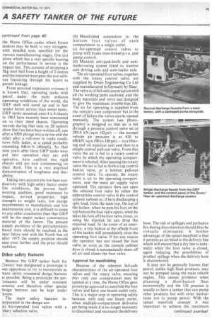
The air for operating is supplied from the vehicle's own compressor but in the event of failure the valves can be opened manually. The system (see photo graphs) is designed so that air is fed through a pressure control valve set at 289.8 kN/ sq m (42psi) — the normal vehicle air pressure is at 620 to 690 kN/ sq m (90 to 100 psi) — to a filter ing and oil injection unit and then to a simple central pull-out valve. From this valve the air is fed to a rotary control valve by which the operating compart ment is selected. After passing the rotary valve the air is fed to both a top control button valve, or a bottom pull-out control valve. To operate, the rotary valve is set to the operating compart ment, and the main air supply valve operated. The operator then can open the selected foot valve by either the appropriate control valve in the control console cabinet or, if he is discharging a split load, from the tank top. On top of the tanker, when he puts his foot on the top button the foot valve opens, when he takes his foot off the foot valve closes, so using his dipstick he can drop the required load. In the event of an emergency, a trip button at the offside front of the tanker will immediately close the operating foot valve. If for any reason. the operator has not closed the foot valve as soon as the console cabinet door is closed it automatically shuts off all air and closes the foot valve.
Approval for manifolding Because of the inherent fail-safe characteristics of the air-operated foot valves and the rotary valve, ensuring that only one compartment may be opened at a time, the Home Office gave prototype approval to manifold the foot valves and have one faucet outlet only. This is a major step in operating safety because, with only one faucet outlet, when multiple-compartment deliveries are being made it is no longer necessary to disconnect and reconnect the delivery hose. The risk of spillages and perhaps a fire during disconnection should thus be virtually eliminated. A further advantage of the spinal manifold is that it permits an air bleed to the delivery line which will ensure that a dry line is automatic when the foot valve is closed, again reducing the possibilities of product spillage when the delivery hose is disconnected.
It may not be generally known that petrol, unlike high flash products, may not be pumped using the main vehicle engine. This causes problems when planning a distribution fleet economically and the UK practice is usually to have a tanker that can pump other products but with strict instructions not to pump petrol. With the spinal manifold concept it was important to achieve the maximum built-in safety. For this reason a pump mounted on the tractive unit and direct driven from the engine would not be suitable, and problems with jumper hose disconnection spillages would also be inherent. A hydraulically driven discharge pump mounted under the tank belly was therefore selected as the safest system.
Some time ago development work with Drum Engineering on liquefied petroleum gas (LPG) pumping had evolved a hydraulic system with a watercooled hydraulic oil heat exchanger incorporated into the engine cooling system. This system had several advantages, not least that it eliminated the large hydraulic oil storage tank used as a heat sink, thus reducing the system weight by in some cases as much as 85 kg (1851b). The Drum system was therefore selected, with a direct-mounted hydraulic pump and an air-controlled power take-off (pto). The pto engagement control is interlinked with the vehicle braking system so that the pto cannot be engaged until the brakeLis in the "park" position; this also means that the vehicle cannot be driven away with the pump engaged because as soon as the brake control is moved out of "park" it disengages the pto. An external button at the nearside of the cab also disengages the pto.
Further problem is to ensure that petrol cannot be pumped accidently and also to avoid jumper hoses with possible product spillages. To overcome this, three air-operated valves have been introduced into the delivery line from the spinal manifold (see photographs). These valves are interlinked to the air control of the pto and vehicle braking system. Valve A is on a tee, off the single delivery line; valve B is placed in the delivery line after the valve A tee; and valve C is on another tee off the delivery line after valve B.
Although sounding complicated, operationally the system is simplicity itself. When the operator engages his pto, valve A opens, allowing product to enter the inlet side of the hydraulically driven discharge pump; and at the same time valve B closes, ensuring that all products have to pass through valve A. Also at the same time, valve C opens, allowing product to flow from the pump to the downstream side of the discharge line. Again, all the systems are fail-safe, and taking the brake out of "park" ensures that the pump drive stops and the pump becomes isolated again.
For gravity discharge of petrol, valves A and C are closed with valve B open, allowing a straight through run. The valves will always remain in this posi tion until the pto is selected for pump discharge. In the event of an air failure, the valves and the pto can be controlled manually. A further advantage of the hydraulic system is that with a control valve near the pump it can be used either for discharge or, by reversing the pump, for loading product, the whole vehicle thus becoming more versatile. A direct pump shaft drive to a tachometer ensures that the correct pump speed is maintained for maximum pump efficiency.
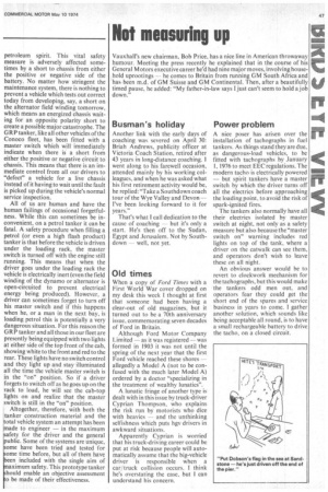
Eliminating swing
For some time now Conoco Ltd has been testing the Maxaret anti-jack-knife system operating only on the drive axle of the tractive unit. Very encouraging results have been obtained with this system although it was recognized that it would not inhibit trailer swing (when the trailer wheels lock and the rear of the trailer tries to overtake the tractor). Dunlop has now developed commercially the Maxaret trailer system working on one wheel of a single-axle trailer, which, by maintaining at least one wheel in rolling contact with the road will control the directional stability of the trailer. It was therefore decided that because of the supervisory control which will be maintained on this prototype GRP tanker it would be the best vehicle on which to assess the Maxaret anti-trailer-swing system thoroughly. It is still far too early to assess this system but reports to date are very encouraging. Studies by the (then) Road Research Laboratory (RRL Report LR325) also indicate that prevention of wheel locking is the better way towards avoidance of jack-knifing.
Other safety features have been incorporated into the tanker which, though not signficant individually, add up to a safety-engineered unit. For instance, it has the four-line braking system which is now standard throughout the Conoco fleet, and has been for some four years. The system ensures that when the driver puts his handbrake in the cab into "park" it also brakes the trailer axle so that all wheels of the complete articulated unit are locked.
Scabbards for dipsticks have always been a thorny problem because the industry practice has been to mount on a rack on the walkway, and in the dark if is easy for a driver to catch his trouser bottom in the dipstick or rack, and trip On the GRP tanker all dipsticks have been inset in the roll-over ridge, completely out of the way of the driver's feet.
The petroleum industry throughoul the UK uses a double-pole electrica system on vehicles for carriage o petroleum spirit. This vital safety measure is adversely affected sometimes by a short to chassis from either the positive or negative side of the battery. No matter how stringent the maintenance system, there is nothing to prevent a vehicle which tests out correct today from developing, say, a short on the alternator field winding tomorrow, which means an energized chassis waiting for an opposite polarity short to create a possible major catastrophe. The GRP tanker, like all other vehicles of the Conoco fleet, has been fitted with a master switch which will immediately indicate when there is a short from either the positive or negative circuit to chassis. This means that there is an immediate control from all our drivers to "defect" a vehicle for a live chassis instead of it having to wait until the fault is picked up during the vehicle's normal service inspection.
All of us are human and have the human failings of occasional forgetfulness. While this can sometimes be inconvenient, on a petrol tanker it can be fatal. A safety procedure when filling a petrol (or even a high flash product) tanker is that before the vehicle is driven under the loading rack, the master switch is turned off with the engine still running. This means that when the driver goes under the loading rack the vehicle is electrically inert (even the field winding of the dynamo or alternator is open-circuited to prevent electrical energy being produced). However, a driver can sometimes forget to turn off his master switch and if this happens when he, or a man in the next bay, is loading petrol this is potentially a very dangerous situation. For this reason the GRP tanker and all those in our fleet are presently being equipped with two lights at either side of the top front of the cab, showing white to the front and red to the rear. These lights have no switch control and they light up and stay illuminated all the time the vehicle master switch is in the "on" position. So if a driver forgets to switch off as he goes up on the rack to load, he will see the cab-top lights on and realize that the master switch is still in the "on" position.
.1.1 Altogether, therefore, with both the tanker construction material and the total vehicle system an attempt has been made to engineer — in the maximum safety for the driver and the general public. Some of the systems are unique, ome have been tried and tested for ome time before, but all of them have een included with the single aim of aximum safety. This prototype tanker hould enable an objective assessment o be made of their effectiveness.