 1
1 2
2 3
3 4
4 5
5 6
6 7
7 8
8 9
9 10
10 11
11 12
12 13
13 14
14 15
15 16
16 17
17 18
18 19
19 20
20 21
21 22
22 23
23 24
24 25
25 26
26 27
27 28
28 29
29 30
30 31
31 32
32 33
33 34
34 35
35 36
36 37
37 38
38 39
39 40
40 41
41 42
42 43
43 44
44 45
45 46
46 47
47 48
48 49
49 50
50 51
51 52
52 53
53 54
54 55
55 56
56 57
57 58
58 59
59 60
60 61
61 62
62 63
63 64
64 65
65 66
66 67
67 68
68 69
69 70
70 71
71 72
72 73
73 74
74 75
75 76
76 77
77 78
78 79
79 80
80 81
81 82
82 83
83 84
84 85
85 86
86 87
87 88
88 89
89 90
90 91
91 92
92 93
93 94
94 95
95 96
96 97
97 98
98 99
99 100
100 101
101 102
102 103
103 104
104 105
105 106
106 107
107 108
108 109
109 110
110 111
111 112
112 113
113 114
114 115
115 116
116 117
117 118
118 119
119 120
120 121
121 122
122 123
123 124
124 125
125 126
126 127
127 128
128 129
129 130
130 131
131 132
132 133
133 134
134 135
135 136
136 137
137 138
138 139
139 140
140 141
141 142
142 143
143 144
144 145
145 146
146 147
147 148
148 149
149 150
150 151
151 152
152 153
153 154
154 155
155 156
156 157
157 158
158 159
159 160
160 161
161 162
162 163
163 164
164 Another Independent Suspension System
Page 124
If you've noticed an error in this article please click here to report it so we can fix it.
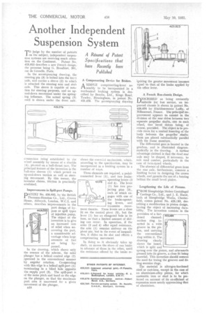
judge by the number of patents on the subject, independent suspension systems are receiving much attention on the Continent. Patent No. 425,923 describes a new French design,the patentee being G. Broalhiet, 201, rue de Grenelle, Paris.
In the accompanying drawing, the steering pin (5) is bolted into the front axle, and carries a sleeve (2) to which is attached the steering arm and stub axle. This sleeve is capable of rotation for steering purposes, and an upand-down movement under the springing influence. The actual spring (3) iised is shown under the front axle.
connection being established to the wheel assembly by means of a shackle (4), pivoted on a ball-thrust race. The principal feature of the invention is the ball-race sleeves (1) which permit an up-and-down motion as well as steering movement. By this means, the inventor claims, friction is practically abolished.
Improvements in Spill-port Pumps.
PATENy No. 426,052, by the British Thoinson-liouston Co., Ltd., Crown House, Aldwych, London, W.C.2, and others, describes improvements in the port design of bypass or spill types of injection pump. The object of the invention is to give an increased rate of relief when uncovering the port, a considerable advantage when large amounts of fuel are being bypassed.
In the drawing, which shows only the essence of the scheme, the solid plunger has a helical control edge (2) operated in the conventional manner by angular rotation. Co-operating with this edge is a helical spill-port (1) terminating in a blind hole opposite the supply port (3). The spill-port is of the same pitch and hand as the edge on the plunger, so that the maximum port area is uncovered for a given movement of the plunger.
is.10 A Compensating Device for Brakes.
tiA SIMPLE compensating-lever assembly to be incorporated in a mechanical braking system is described by Ilendix, Ltd., Kings Road, Tyseley, Birmingham, in patent No. 425,478. The accompanying drawing
shows the essential mechanism, which, according to the specification, may be incorporated in a braking system in a number of ways.
Three elements are required, a pedalconnected lever (1), and two brakeoperating levers (2 and 4). The lever (1) has two projecting pins (3), each of which engages with one of the brake-operating levers, and transmits movement thereto. These levers are a close fit on the Central pivot (5), but the lever ( I ) has an elongated hole in its boss, so that a limited amount of sliding can occur, In operation, if the arms (2 and 4) offer equal resistance, the arm (1) remains midway on the pivot pin, but in the event of inequalities, it slides on its slot and effects a compensating movement.
In doing so it obviously takes up slack, or moves the shoes of one brake in advance of those in the other, until the resistance offered by the brake re -'quiring the greater movement becomes equal to that, of the brake applied by the other lever.
A French Bus-chassis Design.
DESCRIBED as being eminently suitable for bus service, an improved chassis is shown in patent No. 426,076 by Etablissements Laffly, of Billancourt, France. The principal improvement appears to consist in the division of the rear drive between two separate propeller shafts, one to each wheel, two bevel drives being, of course, provided. The object is to provide room for a central lowering of the body between the propeller shafts; these are placed substantially parallel with the frame members, The differential gear is located in the gearbox,and is illustrated diagrammatically in the drawing. -A further advantage claimed is that the dead rear axle may be shaped, if necessary, to suit road camber, particularly in the case of twin-tyred wheels.
The absence of differential gears from the rear axle, furthermore, removes a limiting factor in designing the crown wheels, and permits the use of a bearing behind the small bevel pinion.
Lengthening the Life of Pistons.
FROM Sheepbridge Stokes Centrifugal Castings Co., Ltd., and J. E. Hurst, both of Sheepbridge Works, Chesterfield, comes patent No. 425,C83, describing a modification in piston design, having the object of increasing durability. The invention consists in the provision of a hardened channelsection ring inserted in a wide groove in the piston, and can-ying the conventional ring within it. The drawing clearly shows the insert which is split and sprung over the piston, and afterwards pressed into its groove, a close fit being essential. This invention should remove the need for truing the grooves and fitting oversize rings.
The material is nitrogen-hardened steel or cast-iron, except in the case of an aluminium-alloy piston, for which austenitic iron or steel is to be preferred on account of its co-efficient of expansion more nearly approaching that of aluminium.