


TRAILER TIPPING BY AUTOMATIC MEANS.
Page 72
If you've noticed an error in this article please click here to report it so we can fix it.
A Resurn6 of Recently Published Patent Specifications.
AFORM of tipping trailer which can be tipped by the forward movement of the tractor vehicle to which it is attached, is shown by Clayton and Shuttleworth, Ltd., and T. H. Kempsall in their specification No. 267,717. The trailer is of the two-wheeled class and is provided 'with a castor wheel for steadiment, and to enable it to be moved when. released from its tractor. The draw-bar is formed of two parts, the upper part being provided with a telescopic slide, a locking-pin securing this slide from movement, at the same time connecting up the frame which extemls downwards from the body of the trailer.
In operation the road wheels are secured from movement by a brake of any convenient form, the locking-pin is then released, and the tractor moved a short distance in a forward direction. This has the effect of musing the telescopic slide in the upper draw-bar to move forward, whilst the lower Yt,mber operates the bell-crank lever and causes the body to tip. One of the objects of the invention is to prevent accidents, which sometimes happen when a trailer is backed up te the edge of a bunker or slope for tipping.
Driving Four Wheels of a Six-wheeler. A MEANS for driving two axles of a six-wheeler by means
of bevel gears and a shaft which runs right through the centre of the foremost of the two driving axles is described by Heinrich Blumer, of Zurich, in his specification No. 262,734. The specification admits that a similar arrangement has been used for driving all the wheels of a fourwheeled vehicle, but it claims that no attempt has hitherto been made to secure a direct drive of this kind for the middle and rear axles of a three-axled vehicle.
A central shaft runs right through from the gearbox, and by means of universal joints drives the bevel gear of the rearmost axle. Where it passes the separated shafts of the central axle it is provided with an enlarged portion from which two pins project; being integral with this portion of the shaft they revolve with it. Mounted freely on these pins are two bevel wheels, which engage with bevel wheels formed on the ends of sleeves which are free on the main shaft. Both of these sleeves carry at their outer ends another bevel wheel which engages with a bevel wheel keyed to one of the divided axles of the central pair of road wheels. By this means a shaft is provided, which can run uninterruptedly through the right-angle drive of the central axle without the employment of worm gearing—which arrangement the inventor appears to consider an advantage. The rise and fall of the central axle for uneven ground is .provided for by short axles fitted with universal joints at each end.
It is not easy to see how the necessary reduction between engine and road wheels can be obtained by bevel gearing alone, without using • umitily' large -crown wheels or .too small a pinion. The central road wheels are mounted on steerable pivots to allow for a deviation from a straight course.
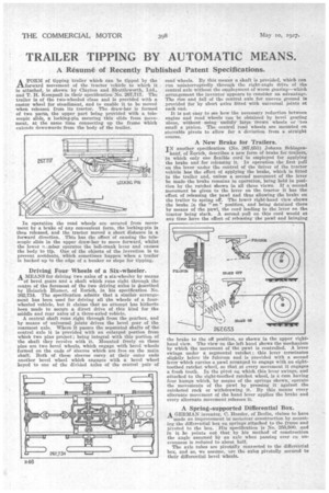
A New Brake for Trailers.
IN another specification (No. 267,653) Johann Schlagen hanf, of Zurich, describes a new form of brake for trailers, in which only one flexible cord is employed for applying the brake and for releasing it. In operation the first pull on the lever under the control of the 'driver of the tractor vehicle has the effect of applying the brake, which is fitted to the trailer and, unless a second movement of the lever be made the brake remains in operation, being held in position by the ratchet shown in all three views. If a second movement be given to the lever on the tractor it has the effect of releasing the pawl and thus allowing the brake on the trailer to spring off. The lower right-hand view shows the brake in. the " on " position, and being detained there by means of the pawl, the cord leading to the lever on the tractor being slack. A second pull on this cord would at any time have the effect of releasing the pawl and bringing the brake to the off position, as shown in the upper righthand view. The view on the left hand shows the mechanism by which the movement of the pawl is controlled. A lever swings under a segmental ratchet ; this lever terminates slightly below its fulcrum and is provided with a second lever which carries a pawl arranged to engage with an eighttoothed ratchet wheel, so that at every movement it engages a fresh tooth. In the pivot on which this lever swings, and attached to the eight-toothed ratchet wheel, is a cam having four humps which, by means of the springs shown, operate the movenients of the pawl by pressing it against the ratcheted rack or withdrawing it. By this means every alternate movement of the hand lever applies the brake and every alternate movement releases it.
A Spring-supported Differential Box. A GERMAN inventor, C. Hessler, of Berlin, claims to have
made an improvement in motorcar construction by mounting the differential box on springs attached to the frame and pivoted to the box. His specification is No. 255,500, and in it he points out that by his method of construction the angle assumed by an axle when passing over en unevenness is reduced to about half.
The axle tubes are pivotally connected to the differential box, and so, we assume, are the axles pivotally secured to their differential bevel wheels.