


MAKING BEST USE OF THE FORD.
Page 62
If you've noticed an error in this article please click here to report it so we can fix it.
Valuable Advice on Every Phase of Ford Transport which will Appeal to the Owner, Driver and Repairer.
504.—An Inspection Cover for the Engine Oil Pipe.
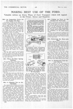
A common trouble in the engine is a blocked oil pipe, and such an occurrence requires considerable time to remedy, and it might easily be the cause of a _bearing running out if not discovered. A simple means, however, is available for obviating the trouble and dispelling any doubt as to the condition of the pipe, whilst the alteration required can be quickly carried out when once the transmission cover is removed.
Measure on the cover a distance of 2e ins, to the right from the centre of the main plug, and at this point drill a 1-in, diameter hole. At a distance of 11 ins, from the centre of this hole drill a second hole lc in, diameter and tap it -ee in. Whitworth. Machine a brass cap similar to that shown in the accompanying sketch and cut a nallite or cork washer to fit it. Next obtain a spring clamp, such as is used to hold in place the make-and-break cover on a magneto,
and secure this by means of a in. screw and a small distance collar. The brass cap is placed over the 1-in, hole and secured by means of a spring clamp.
The cap, when removed, gives access to the oil pipe, which can be cleaned easily by means of a length of wire, and it is advisable to carry out this process at fairly frequent intervals, thus avoiding any risk at all.
505.—When the Rear Spring Flattens.
We recently had a letter from a user of a Ford van asking us what fittings could be employed in conjunction with the rear spring of the van to raise the chassis frame when the spring had flattened out permanently under load. It was mentioned at the same time that previous experience had shown the inadvisability of resetting the spring, as often the retempering is not carried out efficiently.
We took this matter up with the service department of Arthur E. Gould, Ltd., the well-known Ford dealers, of 55-59, Shaftesbury Avenue, London, W.1, and the advice given in this connection was that the only efficient way to rectify this trouble is to fit a new nine-leaf rear spring.
506.—A Slipping Nut on the Camshaft. .
The slipping of a locknut on the Jamshaft often produces symptoms which are misleading to many mechanics, especially those who have not had very much experience with Ford vehicles. The engine usually starts and answers the throttle to a limited extent, but behaves as if it had lost half its power. The plugs will apparently all be functioning properly and the carburetter working satisfactorily, but the compression will appear to be poor, with the result that the mechanic will often suspect valves or piston rings. When such symptoms occur it is advisable to suspect slipping of the camshaft locknut.
It is fortunate that this can more easily be verified on the Ford than on practically any other make. All that it is necessary to do is to remove the commutator case and to utilize a spanner on the. retaining nut of the commutator roller, gently moving it in both direc
tions. Should the movement exceed the amount which may be allowed for play between the teeth of the timing wheels it is obvious that the loanut has worked loose, thus upsetting the timing both of the valves and ignition.
-eeThis state of affairs can be remedied by removing the radiator, starting handle, fan-drive pulley, fan bracket (in the old type) and timing-wheel end plate, which will then expose the timing wheels. . As a rule it will be found that the camshaft dowel pins aisle require renewing.
When reassembling, mesh the zero marks together and see that the inlet on No. 3 cylinder is oven.
There are only two ways of reassembling the valve timing gear, but the wrong way is often followed. 507.—Taking up Wear on the [Radius-rod Ball-ends.
When a front-axle radius-rod ball-end joint becomes worn the wear is usually taken up by filing the bottom bearing cap, but the ball end of the rod and the socket on the crankcase also become worn, sometimes so badly as to throw the axle out of line quite considerably, thus causing wheel wobble, apart from the possibility of the joint coming adrift.
A cure can be effected by utilizing two ball caps in place of one, the extra Pap taking the place of the ball socket in the crankcase and both caps being mounted on the same bolts.
508.—Removing the Rear-axle Hub.
When difficulty is experienced in the removal of the hub from the rear axle, withdrawal can be facilitated if heat be applied around the body of the hub by means of 'a blow-lamp. This should be done fairly thoroughly, and no time should be lost in applying the tool which is being used, particularly if this be a standard Ford wheel puller.
If the puller be of the type which has claws drawing on the rim of the brake drum, thee the heat may be applied to the hub with the tool in situ.
It may be as well to mention that removal will be rendered even more difficult if the hub be allowed to cool, as shrinkage then takes place in the metal.
509.—A Withdrawal Tool for Axle Sleeves.
The problem of the extraction of Ford axle sleeves is one in which a lot of time can be wasted, even when the axle is dismantled, unless some of the special equipment sold for the purpose is at hand. The device shown in the accompanying sketches was made in half an hour and has saved many hours by the number of sleeves it has enabled our contributor to extract.
A piece of steel bar slightly less than the length of the sleeve and as near the internal diameter of a sleeve as possible was obtained; this was put into the lathe and turned down to 3-64 in. less than the sleeve bore. A hale e in. in diameter was drilled, as -shown in Fig. 3, and to three-quarters the diameter of the bar; this was fitted with a spring and plunger as shown, the plunger being a piece of e-in. bolt casehardened. The extractor was then drilled and tapped and fitted with a handle at the outer end, as shown in Fig. 1.
In operation the extractor is pushed into the axle end containing the sleeve, when by turning it round so that the plunger coincides with the lubricator hole in the sleeve the spring pushes the plunger into this hole. The sleeve may then be driven out by passing a bar through the axle casing from the opposite end and driving with a hammer. The slight clearance of 3-64 in. enables the sleeve to contract sufficiently to release the retaining pip on it.