 1
1 2
2 3
3 4
4 5
5 6
6 7
7 8
8 9
9 10
10 11
11 12
12 13
13 14
14 15
15 16
16 17
17 18
18 19
19 20
20 21
21 22
22 23
23 24
24 25
25 26
26 27
27 28
28 29
29 30
30 31
31 32
32 33
33 34
34 35
35 36
36 37
37 38
38 39
39 40
40 41
41 42
42 43
43 44
44 45
45 46
46 47
47 48
48 49
49 50
50 51
51 52
52 53
53 54
54 55
55 56
56 57
57 58
58 59
59 60
60 61
61 62
62 63
63 64
64 65
65 66
66 67
67 68
68 69
69 70
70 71
71 72
72 73
73 74
74 75
75 76
76 77
77 78
78 79
79 80
80 81
81 82
82 83
83 84
84 85
85 86
86 87
87 88
88 89
89 90
90 91
91 92
92 93
93 94
94 95
95 96
96 97
97 98
98 99
99 100
100 101
101 102
102 103
103 104
104 105
105 106
106 107
107 108
108 109
109 110
110 111
111 112
112 113
113 114
114 115
115 116
116 117
117 118
118 119
119 120
120 121
121 122
122 123
123 124
124 125
125 126
126 127
127 128
128 129
129 130
130 131
131 132
132 133
133 134
134 135
135 136
136 137
137 138
138 139
139 140
140 VARIABLE-COMPRESSION ENGINE
Page 96
If you've noticed an error in this article please click here to report it so we can fix it.
AN ENGINE having an adjustable compression ratio forms the subject of patent No. 859,764. (R. George, 67 Avenue Foch, Paris.) The drawing shows the general construction. In addition to the normal combustion space the cylinder has an upward extension (1) forming in effect a second cylinder. The two are joined by a narrow passage.
The volume of the upper chamber is varied by a piston (2) inside a split sleeve. Combustion is initiated in the upper space either by a sparking plug (3) mounted in the upper chamber or by an injector located to inject into the upper chamber.
The auxiliary piston could be downwardly biased by a spring, but it is preferred to use the mechanism shown. This comprises a double rack-and-pinion assembly (4) actuated by an hydraulic piston (5). The hydraulic piston is itself controlled by a smalL constant-pressure pump unit shown generally at 6. Variation of the upper compression space is automatic, through the balancing of the hydraulic pressure and the pressure in the combustion chambers. Pressure surges are damped by a dash pot (7).
An important feature is the hydraulic cylinder shown at 8. The purpose of this is to keep the piston-sleeve on the c58 move at all times to prevent seizure or sticking by carbon. The operating piston is slowly reciprocated at one or two cycles per second, by the rotation of valve (9).
A COLLAPSIBLE VEHICLE
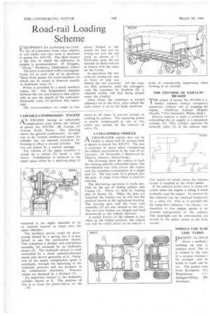
A TWO-SEATER vehicle that can be 1—k folded to about half its normal bulk is shown in patent No. 859,577. The aim is economy in space when transporting the vehicle, particularly in the case of air journeys. (N. Straussler, 2 Boulevard du Theatre, Geneva, Switzerland.)
The drawings show the vehicle in both the running and the collapsible states. The two-wheeled rear axle carries the engine and the complete transmission in a single unit (I). The fuel tank (2) is placed over the axle. A single front wheel is used for steering.
The shortening operation is made possible by the use of sliding tubular side frames (3). These are held by locking pins in blocks (4). When the pins are removed, the frames can be slid into the position shown in the right-hand drawing. The steering gear and the front axle assembly (5) are also moved to the rear. The two seat frames are hinged and fold downwards as the vehicle shortens.
A useful feature of the scheme is that when in the folded position, the vehicle can still be rolled about on its wheels, a THE CONTROL OF EXHAUST BRAKES
THE object of patent No. 859,800 is to render exhaust brakes completely automatic, without risk of stopping the engine. (Fabbrica ltaliana Magnet Marelli, 7 Via Guastalla, Milan, Italy.)
Electric control is used, a solenoid (l controlling the air supply to a pneumatic cylinder (2). This cylinder operates thc butterfly valve (3) in the exhaust pipe The switch (4) which closes the solenoit circuit is coupled to the brake pedal.
If the exhaust brake were to come inti action when the engine is idling it woult probably stop the engine. To prevent thi the solenoid can be rendered inoperativ by a relay (5). This is in parallel witl the lamp that indicates "no charge," an therefore at low engine speeds it wil prevent energization of the solenoic The stop-light can be conveniently con nected to the pedal switch in the brak circuit.
WHEELS FOR TUBf LESS TYRES
pATENT No. 859,38 shows a method c building up rims fc. tubeless tyres. The rit is welded to the whet in a manner claimed t be stronger and In liable to crack and lot air. The patent comi from Kronprinz A.0 Weyestrasse 1 1: Solingen-Ohligs, We Germany.