


Carburetter System for Two Fuels
Page 36
If you've noticed an error in this article please click here to report it so we can fix it.
A Résumé of Patent Specifications That Have Recently Been Published
NUMEROUS attempts have, in the past, been made to run a carbu, retter-fed engine on low-grade fuel, but whilst the method is reasonably Successful with a constant-sPeed engine,, the principle has not been found to be practicable with a throttle-controlled engine. To overcome this difficulty is the object of a scheme shown in patent No. 558,368, by Carbohydrol Ltd. and J. Bracher, both of Star Works, Lyrnm, Cheshire.
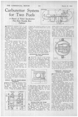
The scheme operates thus: two carburetters are provided, one fed with petrol for starting, idling and accelerating, and another, using a heavier fuel, for the main power output at a governor-controlled speed.
The drawing shows an arrangement suitable for a tractor which is to be run on petrol and paraffin. One carburetter (5) supplies the petrol, whilst the paraffin is dealt with by another (7). The inlet (6) to the engine is• fitted with the usual governor-con trolled throttle. Individual throttle valves (1 and 4) on each carburetter are linked to-gether so that one opens as the other shuts; this action is under the control of the driver.
The main air inlet (8) leads to a looped pipe (2), which connects the inlets of the two carburetters. A strangler valve (3) deals with only the petrol carburetter.
When sfarting, the dual *throttle is set so as to shut off the paraffin carburetter and open the petrol one, at the same time the strangler valve is shut. As the engine warms to its work, the driver can gradually transpose the setting until the engine is running on only paraffin.
DESIGN FOR AN EIGHT-SPEED GEARBOX
FROM David Brown Tractors, Ltd., Meltham Mills, Huddersfield, and E Merritt, comes, in patent No 558,392, a design for a gearbox giving' eight forward speeds and a reverse. Using the minimum number
of gears, the scheme is said to be very suitable for tractors fitted with a power take-off.
Three shafts are employed: the drawing shows these in one plane but, actually, they are positioned at the three points of a triangle. The input shaft (7) is provided with a primary twospeed pinion (1) giving a choice of two ratios with the intermediate shaft (6). A similar two-speed pinion (3) drives the final shaft (4.). This arrangement gives four speeds in all; the other four are obtained via a further two-speed pinion (5) which drives tke final shaft directly from the primary, the gears on the shaft (6) then acting only as idlers. In other words, gears, 3 and 5, provide four speeds upon which gear 1 cad superimpose a high or low value. A reverse pinion (2) drives through an additional idler in the usual manner.
RENDERING BALL BEARINGS OIL-TIGHT
ASEALING ring for a ball bearing forms the subject of patent No, 558,375, from the Hoffmann :Manufac turing Co., Ltd., Chelmsford. The seal serves the double purpose of preventing the escape of lubricant and, at
the same time, excluding dirt. The drawing shoWs part of a bearing with the sealing ring in place. It is made in three parts, a rigid washer (2) and a synthetic-rubber ring (9) bonded on to a rigid centre ring (4). The lastnamed is slidable and is, to some extent, self-aligning.
The outer race is specially formed with a shoulder and groove in its bore, whilst the inner race is stepped to receive freely ring 4. A spring-clip (1) presses the rubber into firm contact with the outer race; whilst the shear stress on the rubber also loads faces 5 to form a running seal.
ROTOR-TYPE OIL PUMP A SIMPLIFIED design for. small
small pump, suitable for lubricating systems, forms the subject of patent No. 558,373, from W. Wheeler and Clifford Motor Components, Ltd., Spring Road. Birmingham, 11. The pump works on the principle of varying the volume of a closed chamber by means of a collapsible member, The driving spindle (2) carries a rotor (1) fitted with a spring-loaded piston (4). The rotor may be cylindrical or, as in the present case, spherical. Due to the eccentrioity of the shaft in relation to the casing, as the rotor revolves the piston is reciprocated by contact with the wall of the casing and, therefore, varies the volume of the casing as a whole. The pumpiti,g action thus set up is converted into a one-way direction by means of a pail of ball-valves (3 and 5).
" HOLD-ON " DEVICE FOR HYDRAULIC BRAKES
PATENT No. 557,981, from Bendix Aviation Corporation, South Bend, Indiana, U.S.A., describes a device for bolding hydraulic brakes in the "'on " position, with the addition of safety devices to prevent operation when it might be dangerous.
.There are several parts to the mechanism; all of which are electrically operated. The actual " hold-on " consists of an electrically controlled valve in the master pipe, which, when energized, obstructs the return flow of fluid and thus holds on the brakes. There are, however, two switches in the circuit, both of which must be closed
before the action can occur., One switch is worked by the pressure of the hydraulic fluid; this may be incorporated with the switch that works the • stop " light. The other switch is worked by the movement of the accelerator pedal; unless this be flee, it can close the circuit.
To prevent a "hold-on" in the event of very heavy braking, the accelerator-pedal switch has a mercury globule which refuses to make contact at rates-of deceleration in excess of 4 ft. per sec, per sec.