


Fuel Injection Without a Highpressure Pump
Page 62
If you've noticed an error in this article please click here to report it so we can fix it.
A Resume of Patent Specifications That Have Recently Been Published
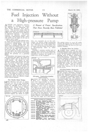
ANOVEL and ingenious injection system is disclosed in patent No. 499,040, by P. Zumbusch, 242, Park Street, Montclair, New Jersey, U.S.A. This inventor states that oil engines, generally, are limited to about 2,200 r.p.m., due partly to the difficulty
of high-speed injection. The patent concerns an injection system, not requiring a high-pressure pump, which will enable an oil engine to be run at a higher speed range.
The drawing shows the injector unit, to which fuel is supplied by the usual low-pressure lifting pump. The unit contains a central sliding stem (3) fitted with a mushroom head (4). The stem is fixed to a sliding guide which is in one with an upper stem carrying a hard steel collar (8) and a disc (1). An outer slider (2), fitted with projecting lugs (7), can be moved downwards against the pressure of a powerful spring. In operation, fuel passes a ball valve and descends into space (6) sealed by a dished washer (5), as shown in the small sketch. By means of camoperated rockers (not shown) the lugs (7) are moved downwardly, to compress the spring. The cam suddenly releases its pressure and the sleeve (2) . is then impelled violently upwards by the spring, to strike the collar (8) with a hammer-blow; this flattens the washer (5) and expels the fuel, from under the mushroom head, in a highly atomized state. The output is varied by turning the disc (1); this, by means of a screw adjustment, alters the effective length of the central member.
New Bendix Brake Design.
HIGH efficiency and ease of adjustment are two of the advantages claimed for a brake design shown in patent No. 499,598, by 3. Irving and Bendix, Ltd., King's Road, Tyseley, Birmingham. In this scheme, each shoe carries a pair of bell-cranks (2) connected by a compression bar (3). Housing 5 contains a pair of wedgeoperated tappets (4) which, in opera
tion, are expanded cm, to the bellcranks, the motion being transmitted to the opposite end by the compression bar. The shoes are, within limits, free to rotate with the drums, and thus have a self-energizing effect in either direction.
Housing 1 contains another pair of tappets; these, however, are stationary, although they can be forced apart, for adjustment purposes by means of a coned screw in the backplate.
Oil-engine Combustion-chamber Improvements, PATENT No. 499,283, 'by DaimlerBenz A.G., Stuttgart, Germany, deals with improvements in its wellknown pre-combustion chamber for oil engines. The patent refers entirely to proportions rather than to principles. The object is to enable the fuel spray to be distributed more evenly over the compressed air, and, to this end, the .piston is provided with a shallow recess (1) into which the injector is pointed at an angle (2) of 79. degrees. Another design employs a flat-topped piston; in this case the angle (2) is 84 degrees
The patent claims to cover all angles between 60 degrees and 90 degrees, in conjunction with the use of a pre-combustion chamber.
A Durable Floor for Lorries.
1-1.
A LORRY floor, capable of with standing hard wear, and free from projecting points which might tear full sacks, is the subject of patent No. 498,216, from A. Hilper, Deula-Kralt, Berlin-Wartenberg, Germany. This inventor employs a wooden under-floor with a top facing of sheet steel. The facing is held down to the wood by spring-loaded bolts (1) which extend through the chassis, and are intended to prevent rattle. The Use of these spring bolts 'appears to be the basis of the patent Attaching Rubber Mudguards.
BEARING the names E. Ottaway and the London PasSenger Transport Board, 55, Broadway, LondOn, S.W.1, patent No. 498,947 discloses a design for a mudguard employing rubber for the forward portion. The patent is concerned chiefly with the methods of . attachment. Referring to the drawing, rear portion (3) is of metal, and is carried by the bodywork of the vehicle, The forward part (1), which is moulded. in rubber, and internally ribbed, is sup-. ported at one point by a frame bracket (4) and at the rear end to the metal section of the mudguard. At this point, the rubber is held in a concave groove (2) by a screw-tensioned draw-wire, which makes a neat and effective joint.