


Self energizing Clutch
Page 70
If you've noticed an error in this article please click here to report it so we can fix it.
A Resume of Recently Published Patent Specifications
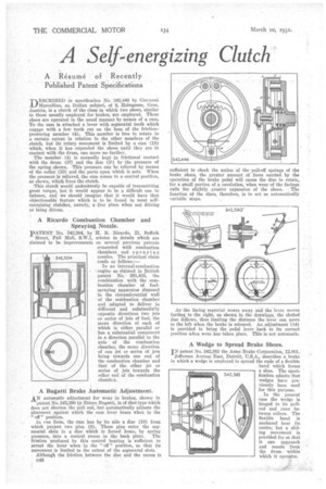
DESCRIBED in specification No. 342,446 by Giovanni Marcellino, an Italian subject, of 8, Helrogasse, Graz, Austria, is a clutch of the class in which two shoes, similar to those usually employed for brakes, are employed. These Shoes are operated in the usual manner by means of a cam. To the cam is attached a lever with segmental teeth which engage with a few teeth cut on the boss of the frictionproducing member (4). This member is free to rotate to a certain extent in relation to the other members of the clutch, but its rotary movement is limited by a cam (18) which, when it has expanded the shoes until they are in contact with the drum, can move no farther.
The member (4) is normally kept in frictional contact with the drum (32) and the disc (31) by the pressure of the spring shown. This pressure can be relieved by means of the collar (10) and the parts upon which it acts. When the pressure is relieved, the cam comes to a central position, as shown, which frees the clutch.
This clutch would undoubtedly be capable of transmitting great torque, but it would appear to be a difficult one to balance, and we should imagine that it would have that objectionable feature which is to be found in most selfenergizing clutches, namely, a free place when not driving or being driven.
A Ricardo Combustion Chamber and Spraying Nozzle.
pATENT No. 342,304, by B. It. Ricardo, 21, Suffolk Street, Pall Mall, S.W.1, relates to details which are claimed to be improvements on several previous patents connected with combustion chambers and spraying nozzles. The principal claim reads as follows :— In an internal-combustion engine as claimed in British patent No, • 261,435, the combination with the combustion chamber of fuelspraying apparatus disposed in the circumferential wall of the combustion chamber and adapted to deliver in different and substantially opposite directions two jets or series of jets of fuel, the mean direction of each of which is either parallel or has a substantial component in a direction parallel to the axis of the combustion chamber, the mean direction of one jet or series of jets being towards one end of the combustion chamber and that of the other jet or series of jets towards the other end of the combustion chamber.
• A Bugatti Brake Automatic Adjustment.
AN automatic adjustment for wear in brakes, shown in patent No. 342,300 by Ettore Bugatti, is of that type which does not shorten the pull rod, but automatically adjusts the abutment against which the cam lever bears when in the of" position.
In ene form, the cam has by its side a disc (10) from which project two pins (8). These pins enter the segmental slots in a disc which is forced home, by spring pressure, into a conical recess in the back plate. The frietion produced by this conical beating is sufficient to arrest the lever when in the " off " position, so that its movement is limited to the extent of the segmental slots.
Although the friction between the disc and the recess is c48 sufficient to check the action of the pull-off springs of the brake shoes, the greater amount of force exerted by the operation of the brake pedal will cause the disc to rotate, for a small portion of a revolution, when wear of the facings.
calls for slightly greater expansion of the shoes. The function of the discs, therefore, is to act as automatically variable stops.
As the facing material wears away and the lever moves farther to the right, as shown in the drawings, the slotted disc follows, thus limiting the distance the lever can move to the left when the brake is released. An adjustment '(14) is provided to bring the pedal lever back to its correct position when wear has taken place. This is not automatic.
A Wedge to Spread Brake Shoes.
iN patent No. 342,383 the Acme Brake Corporation, 12,801, Jefferson Avenue East, Detroit, U.S.A., describes a brake in which a wedge is employed to spread the ends of a flexible band which forms a shoe. The specification admits that wedges have previously been used for this purpose.
In the present case the wedge is hinged to its pullrod and runs between rollers. The flexible band is anchored near its centre,' but a sliding movement is provided for so that it can approach and recede from the drum . within which it opera.tes.