 1
1 2
2 3
3 4
4 5
5 6
6 7
7 8
8 9
9 10
10 11
11 12
12 13
13 14
14 15
15 16
16 17
17 18
18 19
19 20
20 21
21 22
22 23
23 24
24 25
25 26
26 27
27 28
28 29
29 30
30 31
31 32
32 33
33 34
34 35
35 36
36 37
37 38
38 39
39 40
40 41
41 42
42 43
43 44
44 45
45 46
46 47
47 48
48 49
49 50
50 51
51 52
52 53
53 54
54 55
55 56
56 57
57 58
58 59
59 60
60 61
61 62
62 63
63 64
64 65
65 66
66 67
67 68
68 69
69 70
70 71
71 72
72 73
73 74
74 75
75 76
76 77
77 78
78 79
79 80
80 81
81 82
82 83
83 84
84 85
85 86
86 87
87 88
88 89
89 90
90 91
91 92
92 93
93 94
94 95
95 96
96 97
97 98
98 99
99 100
100 101
101 102
102 103
103 104
104 105
105 106
106 107
107 108
108 109
109 110
110 111
111 112
112 113
113 114
114 115
115 116
116 117
117 118
118 119
119 120
120 121
121 122
122 123
123 124
124 125
125 126
126 127
127 128
128 129
129 130
130 131
131 132
132 133
133 134
134 135
135 136
136 137
137 138
138 139
139 140
140 141
141 142
142 143
143 144
144 145
145 146
146 147
147 148
148 149
149 150
150 151
151 152
152 153
153 154
154 155
155 156
156 An Opposed-piston Oil Engine
Page 108
If you've noticed an error in this article please click here to report it so we can fix it.
A MULTI-CYLINDERED two-stroke rA oil engine in which a pair of opposed pistons works in each cylinder is shown in patent No. 727,233, by Research Engineering Corp., La Porte, Indiana, U.S.A.
The patent makes several interesting observations -on the design of such engines. It is desirable to have the exhaust ports to open before the inlet, but it is undesirable to have them close later. Unfortunately, these two features usually go together. It is of course possible to time the two pistons out of phase and in that way obtain early opening and early closing, but this system results in unbalanced masses and consequent vibration.
The scheme shown employs a rotary ,valve.to time the exhaust closing and so avoid the foregoing defects. Referring to the drawing, each piston (1) has its own crankshaft (2) and all cranks are bevel-geared as shown at 3 to the central power shaft.
Each cylinder has a set of wall ports (4) for the scavenging air which comes from the surrounding manifold. Exhaust ports (5) are also provided; they are placed closer to the central plane so that they are uncovered before the inlets. The exhaust ports discharge into a manifold (6) but this is a closed chamber, and its opening to the atmosphere is controlled by a rotary valve (7). This valve is a ported cylinder and, as it turns, opens or closes the final exhaust exit.
The action is to permit the free escape of the gases to the atmosphere at first, then the rotary valve closes and although the piston has not re-covered the ports, scavenging air can enter and build up a pressure.
AN ITALIAN CARBURETTER
ACARBURETTER in which the mixture, once formed, is subjected to several changes of direction, is shown in patent No. 728,535, by 0. Benvenuti, 90 Via Niccolo da Uzzano, Florence, Italy.
The patent describes only the main mixing arrangements, no details of slow-running jets, or float-chamber being given. As will be seen from the drawing, the whole unit is annular in at 8 outline and is fitted with the usual butterfly throttle (1).
Petrol arriving via pipe 2 reaches orifice 3 and flows into the main air stream arriving from an upper inlet. The mixture flows at high velocity to the bottom of the central tube and passes through numerous cuts (4) to flow upwards again.
It then passes through a central perforated disc and emerges from holes (5) in a conical member. Its direction is again reversed as it makes its way to the bottom exit.
An unusual feature is the provision of blow-off valves (6) in case the internal pressure should rise above atmospheric.
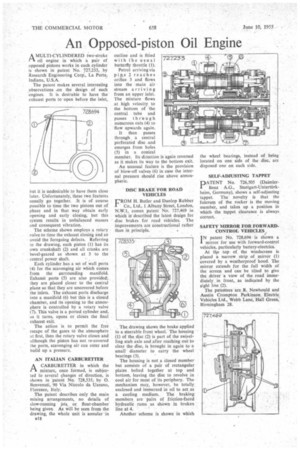
DISC BRAKE FOR ROAD VEHICLES
El ROM H. Butler and Dunlop Rubber Co., Ltd., 1 Albany Street, London, N.W.1, comes patent No. 727,469 in which isdescribed the latest design for disc brakes for road vehicles. The improvements are constructional rather than in principle.
The drawing shows the brake applied to a steerable front wheel. The housing (1) of the disc (2) is part of the swivelling stub axle and after reaching out to clear the disc, is brought in again to a small diameter to carry the wheel bearings (3).
The housing is not a closed member but consists of a pair of rectangular plates bolted together at top and bottom, leaving the disc to revolve in cool air for most of its periphery. The mechanism may, however, be totally enclosed and immersed in oil to act as a cooling medium. The braking members are pairs of friction-faced hydraulic rams as shown in broken line at 4.
Another scheme is shown in which the wheel bearings, instead of being located on one side of the disc,' arc disposed one on each side.
SELF-ADJUSTING TAPPET
PATENT No. 726,505 (DaimlerBenz A.G., Stuttgart-Unterttirkheirn, Germany), shows a self-adjusting tappet. The novelty is that the fulcrum of the rocker is the moving member, and takes up a position in which the tappet clearance is always correct.
SAFETY MIRROR FOR FORWARDCONTROL VEHICLES
I N patent No. 728,694 is shown a mirror for use with forward-control vehicles, particularly battery-electrics. At the top of the windscreen is placed a narrow strip of mirror (1) covered by a weatherproof hood. The mirror extends for the full width of the screen and can be tilted to give the driver a view of the road immediately in front, as indicated by the sight line (2).
The patentees are R. Newbould and Austin Crompton Parkinson Electric Vehicles Ltd., Webb Lane, Hall Green, Birmingham 28.