


CONTROL OF THE DIFFERENTIAL.
Page 24
If you've noticed an error in this article please click here to report it so we can fix it.
A Résumé of Recently Published Patent Specifications.
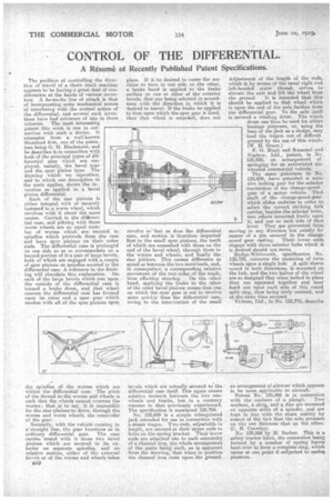
The problem of controlling the direction of travel of a chain track machine appears to be having a great deal of con-. sideratiou at the hands of various inventors. A favourite line of attack is that of incorporating some mechanical means of interfering with the normal action of the differential, and several such inventions have had reference of late in these columns. The most interesting patent this week is one in connection with such a device. It emanates from a well-known Stamford firm, one of the paten. tees being G. M. Blackstone, .and he describes it in connection with both of the principal types a differential gear which are employed, namely, the bevel type and the spur pinion type. The drawing which we reproduce, and to which our description in the main applies, shows the invention as applied to a bevel pinion differential. Each of the star pinions is either integral with or securely fastened to a worm wheel,. which revolves with itaboutthe smile centre. Carried in the difIerential case, and gehring with these worm wheels are an equal number of worms which are secured to spindles which protrude from the case and have spur pinions on their outer ends. The differential case is prolonged on one side so as to accommodate on a turned portion of it a pair of Large bevels, both of which are engaged with a couple of spur pinions on spindles secured to the differential case. A reference to the drawing will elucidate this explanation. On each of the large bevels which run upon the outside of the differential case is turned a brake drum, and that wheel nearest the differential case has formed upon its outer end a spur gear which meshes with all of the spur pinions upon, the spindles of the worms which are within the differential case. The pitch of the thread in the worms and Wheels is such that the wheels cannot overrun the worms; that is to say, it is impossible for the star pinions to drive, through the worms and worm wheels, the remainder of the gear.
Normally, with the vehicle sunning in a' straight line, the gear functions as in ordinary differential gear. The case carries round with it those two bevel pinions which are secured to its exterior on separate spindles, and no relative motion, either of the external bevels or of the. worms and wheels takes B52 place. If it be desired to cause the machine to turn to one side or the other, a brake band is applied to the brake surface on one or other of the exterior bevels, that one being selected in accordance with the direction in which it is desired to travel. If the brake be applied to that upon which the spur gear is fixed, then that wheel is retarded, does not revolve so'fast as does the differential case, and motion is therefore imparted first to the small spur pinioni, the teeth of which are enmeshed with those on the end of the bevel wheel, through them to Una worms and wheels, and finally the star pinions. This causes difference in speed as between the two sunwheels, and, in consequence. a corresponding relative movement of the two sides of the track, thus effecting steering. On the +Alice hand, applying the brake to the other of the outer bevel pinions causes that one on which the spur gear is cut to revolve more quickly than the differential case, owing to the intervention of the small bevels which are actually secured to the. differential case itself. This again causes relative moment between the two sunwheels and tracks, but in a contrary manner to that previously experienced. The specification is numbered 125,794. .
No. 12,5,699 is a simple triangulated jack intended for use in connection with a steam wagon. Two rods, adjustable in length, are secured at their upper ends to bolts on the spring bracket. Their lower ends are attached one to each extremity of a channel iron, the whole arrangement of the parts being such, as is apparent from the drawing, that when in position the channel iron rests upon the ground., Adjustment of the length of the rods, which is by means of the usual right mid left-handed screw thread, serves to elevate the axle and lift the wheel from the ground. It is intended that this should be applied to that wheel which is upon the end of the axle further from the differential gear. To the axle aself is secured a winding drum. The winch drum can then be used for either haulage purposes, or, using the base of the jack as a sledge, may haul the wagon out of difficult ground by the use of this winch. (W. H. Green.)
P. G. Hugh and Scammel and Nephew, Ltd., patent, in No. 125,838, an arrangement of springing for an articulated sixwheeled commercial vehicle.
The same patentees in No. 125,839, have patented a positive locking gear for the selector mechanism of the change-speedgear of a motor vehicle. That shaft of the change-speed-gear which slides endwise in order to select the correct striking fork carries, besides the selector lever, two others mounted freely upon it, and one on each side of that lever. They are prevented from moving in any direction but axially by means of a pin secured in the change speed gear casting. Their lower erids engage with those, selector forks which ib is desired should not move.
Rudge-Whitworth, specification No. 125,739, .concerns the mounting of twin wheels upon a single hub. A split sleeve coned in both directions, is mounted on the hub, and the two halves of the wheel
are so designed that when bolted in place they are squeezed together and bear hard one -upon each side of this coned split ring, thus being truly centred, and at the same time secured.
Vickers, Ltd., in No. 125,775, describe an arrangement of silencer which appears to be more applicable to aircraft.
Patent No. 125,806 is in connection with the coultera of a plough: Two coulters, a skirs,o and a disc are mounted on opposite sides of a spindle, and are kept in line with the share mainly by reason of the fact that the side pressure on the one Valances that on the ther. (C. H. Crawley). No. 125,844 by M. Barker. This is a safety tractor hitch, the connection being formed by a number of spring leaves bent over to'form a complete ring, which opens at one point if subjected to undue pressure.