


ACCURACY TI MORSE CODE
Page 42
Page 43
Page 44
Page 45
If you've noticed an error in this article please click here to report it so we can fix it.
Morse Inverted-tooth and Roller Features ; in Consequence, the Met
Including Those for Insuring .
'hams Incorporate Certain Unique Is Employed in Their Manufacture, :uracy, are Especially Interesting
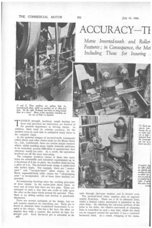
TENSILE strength, hardness, ample bearing surfaces and provision for lubrication are features of the greatest importance in driving chains. In addition, there must be extreme accuracy, for the smallest error in each link is multiplied many times in the complete chain.
In the patented designs of inverted-tooth (commonly called silent) and roller chains made by the Morse Chain Co., Ltd., Letchworth, there are certain unique features which, whilst enabling many highly desirable attributes to be embodied, present difficulties of manufacture that otherwise would not arise. As a result, the operations involved are all the more interesting.
The company produces chains of these two main types for automobile and industrial requirements up to a maximum of 3 ins, in pitch, the smallest chain having a pitch of i in. The inverted-tooth design is subdivided into further types. For example, there are " rockerjoint " and "no-back-bend" silent chains. In the Morse segmental-bush roller chains the "oil-pumping joint" is incorporated. All of these three features are patented.
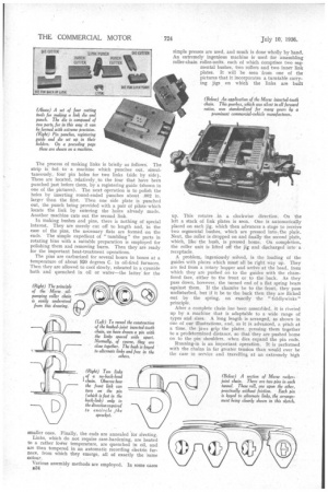
Accompanying drawings show the working principles of these chains. In the rocker-joint silent chain, at each end of every link there are two pins. These are arranged in such a way that one rocks or rolls upon the other as the chain bends around the sprocket. Thus, there is no sliding motion and friction is practically eliminated.
There are several variations of the design, but we will content ourselves by describing one. Each pin is keyed in alternate links (considered transversely in respect of the chain). One has a flat face, the other an angular face with a narrow, flat portion to take the straight pull. Each flat-faced pin is extended at its .B32
ends through disc-type washers and is riveted over.
The no-back-bend chain employs pins of approximately D-section. These are a fit in alternate links, whilst a limited rotary movement is permitted in the other links. By offsetting the cut-away portions of the holes in the latter, the relative movement of adjoining links is controlled in such a way that, whilst the chain can be wrapped around the sprocket, it has a restricted backward bend. As a result, whipping of the chain, which greatly accelerates wear, is effectively checked.
Additional advantages of the use of a D-section pin are that it can be made stouter than a round pin, and it has a larger area of contact on the loaded side. In this connection, it is worthy of mention that if a circular pin be used in a circular hole, there must be clearance between them, with the result that, theoretically, with a new chain, the pin makes only line contact with the walls of the hole. With a D pin, no clearance is necessary and the whole of the corresponding areas are in contact from the commencement.
There is yet a third patented design of inverted-tooth chain in which half bushes—that is, bushes split axially —are used in conjunction with circular pins. The bushes are a tight fit in alternate links, but free to turn a limited amount in the other links, in the outside pair of which the pin is secured. In this way, the load and the motion are between the bush and the pin along the full width of the chain.
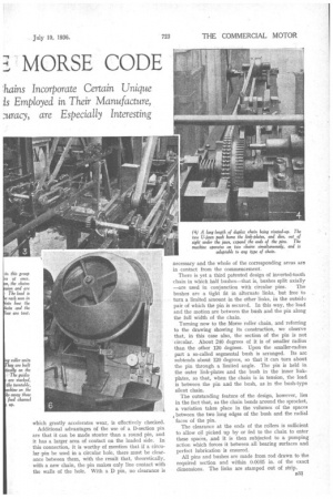
Turning now to the Morse roller chain, and referring to the drawing showing its construction, we observe that, in this case also, the section of the pin is not • circular. About 240 degrees of it is of smaller radius than the other 120 degrees. Upon the smaller-radius part a so-called segmental bush is arranged. Its arc subtends about 120 degrees, so that it can turn about the pin through a limited angle. The pin is held in the outer link-plates and the bush in the inner linkplates, so that, when the chain is in tension, the load is between the pin and the bush, as in the bush-type silent chain.
The outstanding feature of the design, however, lies in the fact that, as the chain bends around the sprocket, a variation takes place in the volumes of the spaces between the two long edges of the bush and the radial faces of the pin.
The clearance at the ends of the rollers is sufficient to allow oil picked up by or fed to the chain to enter these spaces, a.nd it is then subjected to a pumping action which forces it between all bearing surfaces and perfect lubrication is ensured.
All pins and bushes are made from rod drawn to the required section and within 0.0005 in. of the exact dimensions. The links are stamped out of strip.
The process of making links is briefly as follows. The strip is fed to a machine which punches out, simultaneously, four pin holes for two links (side by side). These are located, relatively to the four that have been punched just before them, by a registering guide (shown in one of the pictures). The next operation is to polish the holes by inserting round-ended punches about .002 in. larger than the first. Then one side plate is punched out, the punch being provided with a pair of pilots which locate the link by entering the holes already made. Another machine cuts out the second link.
In making bushes and pins, there is nothing of special interest. They are merely cut off to length and, in the case of the pins, the necessary flats are formed on the ends. The simple expedient of "tumbling" the parts in rotating bins with a suitable preparation is employed for polishing them and removing burrs. Then they are ready for the important heat-treatment operations.
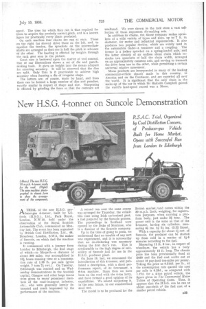
The pins are carburized for several hours in boxes at a temperature of about 920 degrees C. in oil-fired furnaces. Then they are allowed to cool slowly, reheated in a cyanide bath and quenched in oil or water—the latter' for the simple presses are used, and much is done wholly by hand. An extremely ingenious machine is used for assembling roller-chain roller-units, each of which comprises two segmental bushes, two rollers and two inner link plates. It will be seen from one of the pictures that it incorporates a turntable carrying jigs on which the links are built up. This rotates in a clockwise direction. On the left a stack of link plates is seen. One is automatically placed on each jig, which then advances a stage to receive two segmental bushes, which are pressed into, the plate. Next, the roller is dropped on and finally the second plate, which, like the bush, is pressed home. On completion, the roller unit is lifted off the jig and discharged into a receptacle_ A problem, ingeniously solved, is the loading of the guides with plates which must all be right way up. They are fed from a rotary hopper and arrive at the head, from which they are pushed on to the guides with the chamfered face, either to the front or to the back. As they pass down, however, the turned end of a flat spring bears against them. If the chamfer be to the front; they pass undisturbed, but if it be to the back then they are flicked out by the spring, on exactly the "tiddlywinks" principle.
After a complete chain has been assembled, it is riveied up by a machine that is adaptable to a wide range of types and sizes. A long length is arranged, as shown in one of our illustrations, and, as it is advanced, a pitch at a time, the jaws grip the plates, pressing them together to a predetermined distance, so that they are pushed home on to the pin shoulders, when dies expand the pin ends.
Running-in is an important operation. It is performed with the chains in far greater tension than would ever he the case in service and travelling at an extremely high speed. The time for which they run is that required for them to acquire the precisely correct.pithh, and is a known figure for practically every chain produced. On each machine four chains, are run at once. Those on the right (as shown) drive those on the left, and, to equalize the tension, the sprockets on the intermediate shafts are arranged so that one is half the pitch in advance 'of the other. The loading is effected by weights through the rack gear seen in the picture.
Great care is bestowed upon the ma ti-er of tool control. One of our illustrations shows a set of die and punch. making tools. It gives an insight into the means adopted for ensuring accuracy. It will be observed that the dies are split. Only thus is it practicable to achieve high accuracy when forming a die of irregular shape.
The cutters are, of course, made by hand, and from them can be formed a large number of dies and punches, exactly similar in respect of shape and size. Sharpening is effected by grinding the faces so that the contours are unaltered. We were shown in the tool store a vast collection of these important die-making sets. ' In addition to chains, the Morse company makes sprockets of a wide variety of types and sizes, up to 7 ft. in diameter, for motor and industrial requirements. It also produces two popular devie:es, which are widely used in the automobile trade—a tensioner and a coupling. The former is a jockey sprocket on a spring-loaded axle, and the latter consists of an endless silent chain which encircles two sprockets of half the chain width, arranged on an approximately common axis, and serving to transmit the drive from 'one to the other, while permitting a certain universal relative movement.
Morse products are incorporated in many of the leading commercial-vehicle chassis made in this country, in America and on the Continent, and are exported all over the world. It is significant that the only chain in tha make-up of the car in which Sir Malcolm Campbell gained the world's land-speed record was a Morse.