


EQUIPPING A COACH FOR WIRELESS RECEPTION.
Page 14
Page 15
If you've noticed an error in this article please click here to report it so we can fix it.
The Phenomenon of Reaction and the Use to Which* May be Put in Order to Simplify a Circuit whilst Obtaining the Greatest Practical Efficiency.
HIS IS the fifth article upon the subject of equipping a motor coach with the, necessary apparatus and accessories so that entertainments broadcasted during certain hours of the day from the broadcast stations can be received for the edification of the passengers. In the first three 'articles we covered the details of the aerial and earth—the form they should take and the mode of leading the current to the dashboard of the vehicle. In the fourth article (which appeared in the issue of The Commercial Motor for June 26th) we began to deal with the second phase of the problem of equipment--the choice and, installation of the set, and to show why we must employ the valve-typo of receiver. We pointed out that the crystal set, although excel-. lent' for reception over short distances, would riot answer our purpose because of the restricted nature of the aerial and of the ever varying distances at which we shall require reception.
However, if -we set up a circuit, such as that described in that article, we shall .find that the results we obtain are very little better than those given by a simple crystal set, albeit the valve receiver is much more stable and reliable. The reason for this is not far to seek. As we pointed out, we get the effect of sound in our telephones by making use of the difference between the positive and negative sides of our high-frequency oscillations. Now, under the most favourable conditions this difference is very small, amounting as it-does to but a few hundredths of a milleampere—which is one thousandth of an ampere—and so, although the amount of current being handled by the valve may be considerable, only a small portion of it is of any use to us. If we could makesome use of all the unrectified high-frequency current which is flowing in the plate circuit of the valve (and on account of which, i will be remembered, we are obliged to furnish a by-pass condenser across the telephones), we would be able greatly to augment the efficiency of our receiver. As a matter of fact, it is now known that we can do so, and the method by which we accomplish this desirable end is known as "reaction."
B30 The grid of our valve is rendered first positive and then negative by means of the high-frequency currents generatedin the aerial by the passing ether waves. These -currents are, however, extremely small and they are further attenuated by the resistance of the aerial and the inductance connected thereto, so that the amount of energy they liberate in the plate circuit is also small. But we have shown that the unidirectional pulses in the plate circuit are in step with the high-frequency currents in the aerial, and so, if we feed a portion of them back into the aerial circuit, we should be able to bolsten up the weak aerial currents and thus energize the grid more strongly. This, in turn, would cause an increase in the plate current, which would again , react on the aerial circuit to cause a further increase, and so, theoretically, there should be no limit to what we could get out of a valve other than its maximum. current-carrying capacity. We cannot, however, boost matters up to this pitch, for a reason that, will be explained later on, but we can, by means of reaction, increase the sensitivity of our receiver, to an enormous extent.
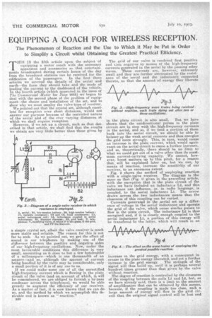
Fig. 2 shows the method of employing reaction with a single-valve receiver. The diagratn is the same as that (Fig. 1) given in the preceding article, with the exception that in the plate circuit of the valve we have included an inductance L2, and this inductance can influence, or, in radio language, is i coupled, to the aerial nductance Li. The arrow drawn across the two inductances means that the closeness of this coupling can be varied.
Currents generated in the aerial set up a difference of voltage in the aerial inductance and operate the grid of the valve, which cause similar pulses to i flow n the plate circuit. The inductance L2 is thus energized and, if it is closely enough coupled to the aerial inductance Li, a portion of this energy will be transfered to the latter, which will result in an
increase m the grid energy, with a consequent increase in the plate energy liberated, and yet a further increase in the grid energy. The strength of the signal will thus build up, until it is perhaps several hundred times greater than that given by the valve without reaction.
The degree of reaction is controlled by the closenessof the coupling between the coils LI and L2, but, as we have already said, there is a limit to the amount of amplification that can be obtained by this means, because, if the coupling is made too close, such a large amount of energy will flow in the grid circuit that the original signal control will be lost and the valve will start oscillating on its own at a frequency dependent upon the constants of the circuits attached to it.
This condition is to be avoided at all costs, because not only is it impossible to. receive intelligible speech and music when the valve is oscillating, but, in this latter condition, the receiver is turned into a transmitter and starts to radiate high-frequency waves which interfere with every other receiver for miles around.
The ideal to be aimed at in the use of reaction is to adjust the coupling of the two coils until the valve is a point just short of oscillation. It is then in its most sensitive condition without interfering.
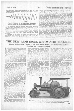
Figs. 2, 4 and 5 show diagrammatically what takes place. Fig. 3 shows a series of wave-trains being received without reaction. Owing to the damping due to resistance in the aerial circuit, each train dies out after two or three oscillations. In Fig. 4 we employ reaction up to the permissible limit, and it will be seen that the result now is to reduce the damping so that each train dies out just before the next one arrives. In Fig. S is shown what happens if reaction be pushed too far. Here' after the first oscillation is received, the subsequent ones actually increase in amplitude until, after two or three, the valve settles down to oscillate steadily. Reaction is a delicate thing to handle satisfactorily, and its misuse in the hands of inexperienced people can cause grave inconvenience to other listeners-in. For this reason it is quite rightly prohibited in the form shown in Fig. 2 on all broadcasting wavelengths during the time that broadcasting is in progress. A modified form that is less objectionable is, however, permitted, and this will be described when we come to consider the "modus operandi" of sets with more than one valve.