


A New Application of Steam.
Page 3
Page 4
If you've noticed an error in this article please click here to report it so we can fix it.
Interesting Particulars of the Flader Front-driven Fire Engine.
In our issue of October 4th, Noti, we published an illustration ot Herr E. C. Elader's front-driven steam fire-engine at practice in Metz, and are now enabled to give some further particulars of this system of transmission.
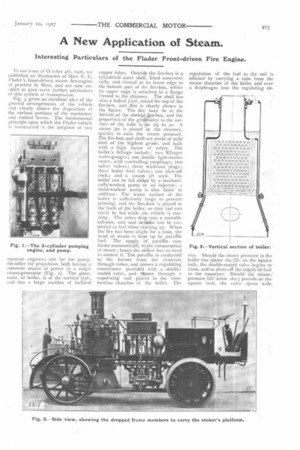
Fig. 3 gives an excellent idea of the general arrangements of the vehicle and clearly shows the disposition el the various portions of the machinery and control levers. The fundamental principle upon which the Hader vehicle is constructed is the adoption of two separate engines; one for the pump, the other for propulsion, both having a common source of power in a single steam-generator (Fig. 2). The generator, or boiler, is of the vertical type, and has a large number of inclined
copper tubes. Outside the fire-box is a cylindrical outer shell, fitted concentrically, and riveted at its lower edge to the bottom part of the fire-box, whilst its upper edge is attached to a flange riveted to the chimney. The shell has also a bolted joint, round the top of the fire-box, and this is clearly shown in the figure. The fire bars lit at the bottom of the conical. ire-box, and the
proportion of the grate...area to surface of the tube is as .65 to to. A steam jet is placed in the chimney, quickly to raise the steam pressure. The fire-box and shell are made of mild steel of the highest grade, and built with a high factor • of. safety. The boiler's fittings include : two Klinger water-gauges; one double light-manometer, with controlling couplings; two safety valves; three wash-out plugs; three boiler feed valves; one blow-oil cock; and a steam. jet cock. The boiler can be fed either by a mechanically-worked pump or an injector; a hand-worked pump is also fitted in addition. The water surface of the boiler is sufficiently large to prevent priming, and the fire-door is placed at the back of the boiler, so that fuel can easily be fed while the vehicle is running. The ashes drop into a movable ash-pan, and coal orfokke can be employed as fuel when starting up. When the fire has been alight for a time, the head of steam is kept up by paraffin fuel. The supply of paraffin conforms automatically to,the consumption of steam ; hence the stiiker has no need to control it. The paraffin is conducted to the burner from the reservoir through tubes, and passes a regulating contrivance provided with a doubleseated valve, and thence through a vaporising coil placed in the combustion chamber of the boiler. The
regulation of the fuel to the coil is effected by carrying a tube from the steam chamber of the boiler and over a diaphragm into the regulating de
vice. Should the steam pressure in the boiler rise above 162.711). on the square inch, the double-seated valve begins to. close, arid so shuts off the supply of fuel to the vaporiser: Should the steampressure fall below 162.7 pounds on the square inch, the valve opens wide,
enough to admit an increased quantity of fuel, which is forced from the reservoir by carbonic acid pressure.
The burner is easily taken down, and is so constructed that it can be attended to at any time with an unprotected hand. The steam pump has three cylinders, and these are cast integrally with the pump body. 1)-slide
are employed, and these are actuate ! by an adjacent valve rod, in a similar way to a Worthington pump. Th, stuffing-boxes of both the pistons and the slide-rods have screw threads, so that they can be tieduened up by hand while the machine is working. Particular attention has been directed to the accessibility of the water valves, no spanner being required for removing them. To accomplish this, a suction and a pressure valve form one unit. The valves are made from dermatine, and are capable of standing a constant pressure of 2641b. on the square inch. Between the delivery and suction chambers there is a device which allows of the water delivery being varied from zero to the maximum 'without altering the number of engine revolutions. The vacuum and sucelon chambers are fitted with gauges, as shown in Fig. t. A lubricating apparatus, with dist lbutin.;
pipes to the various bearings of the steam-pump engine, is fitted upon the top of the cylinders. The water pump will deliver at the rate of 405 gallons a minute to a height of 45 yards, with the engine running at zso revolutions per minute ; the engine is 42h.p. The chassis is built of wrought iron, and the side members are curved downwards at the back to carry the footboards. The entire super-frame rests upon strong springs, which, by an ingenious coupling of the axles to the frame, are relieved from the drag of the front wheels. Stout jointed rods connect up the axles in such a way that no strains are set up when the vehicle is running upon the road. Beneath the driver's seat, at the front of the vehicle, is placed a water tank, having a capacity of so gallons. On the stoker's platform is a petroleum tank, carbonic acid containers, and water and coal boxes. The back wheels are furnished with shoe brakes, actuated from the driver's seat by a lever. Where rubber tires are used the brakes act on drums cast upon the naves. The back wheel hubs are furnished with Moffat's roller bearings.
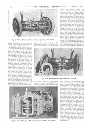
The engine for the propulsion of the vehicle is in the fore carriage. It has four cylinders, arranged in two pairs ; one pair is for each wheel, as shown in Figs. 4 and 6. The crankshafts are vertical, and the upper end of each carries a pinion (Figs. 4 and 5), which meshes with a gear ring on the inner side of the wheel. The front-wheel steering centres are coincident with the centres of the crankshafts, and the steering bearings are, in reality, collars which encircle the upper and lower end hearings of the crankshafts. The hub of the driving wheels is of very large dimensions, and has a diameter corresponding to the distance apart of the steering collars. Between this hub and the fixed central portion of the wheel is interposed a ball bearing to reduce undue friction. Reversing is effected by shifting a single eccentric to each cylinder, as seen in Fig, 6. All the working parts of the propelling motors run in an oil-bath. As in the case of the steering, speed is regulated from the driver's seat. The driving motors develop 6oh.p. at 65o revolutions per minute, and the engine will climb a gradient of 15 per cent. at 20 miles per hour. The steering-rod connections can he seen, clearly, in Fig. 4, and the weight of the whole vehicle is about 4 tons.