


Air operated brakes
Page 37
Page 38
If you've noticed an error in this article please click here to report it so we can fix it.
ON HEAVY commercial vehicles the force that must be exerted on the brake pedal to bring a vehicle to rest quickly is greater than a man can exert, and the driver must be given some assistance in applying the brakes.
This may be done in two ways either by adding a "servomechanism, which assists the driver's effort, although he still supplies much of the necessary -push-, or by using "power Operation", in which case the driver exerts a controlling effort only.
In the latter type the power the driver exerts in operating the brake is not transmitted to the brakes at all; when he presses the brake pedal he just opens a valve and the brakes are applied for him.
Servo mechanisms will be considered later, but as "power operation" (that is air brakes) are almost universal on the heavier commercials which many readers use and maintain, this system will be considered first.
Air brake systems comprise the following components: (1) An engine driven air compressor.
(2) An air filter for the compressor complete with a de-icer.
(3) A reservoir to store the compressed air.
(4) An unloader valve which lifts the inlet valve of the compressor off its seat when the working pressure is reached, so that the compressor runs "light-.
(5) A safety valve in case the unloader valve fails to function.
(6) A brake pedal valve.
(7) Steel and flexible pipes to connect the various units.
(8) Operating brake cylinders for the brake assembly on each wheel.
(9) An air pressure gauge mounted in the driver's cab.
(10) A buzzer which will sound to warn the driver when the air pressure is getting low.
(11) Check valves to prevent the back flow of compressed air.
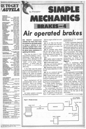
A simple system showing a brake operating on one wheel only is shown in Figure 1.
The compressor may be a single or twin cylinder machine, belt or gear driven off the engine. Its capacity must be such that it will supply sufficient compressed air for repeated brake operation.
A filter is generally fitted to it to ensure a clean supply of air. An anti-freeze device which feeds small quantities of methanol (methyl alcohol) into the air drawn into the compressor is often incorporated. This lowers the freezing point of any moisture in the air and prevents the system from freezing up. A compressor as fitted to a Gardner engine is shown in Figure 2.
Two or sometimes three reservoirs are often fitted; on some vehicles one reservoir is divided into two compartments instead of two separate tanks being used.
This duplication of air storage ensures that if one system fails there is another to fall back on.
It also enables the designer to bring a reservoir nearer to the brake cylinders, as, in the case of very long vehicles, such as maximum length artics, there would be a considerable loss in efficiency if a reservoir at the front of the vehicle had to proI vide the braking power for the brakes on the rear axle of the semi-trailer.
It is essential in an air brake system that the driver can judge the intensity of the brake application accurately, and this means that the rate of retardation of the vehicle must be proportional to the force he exerts on the brake pedal.
The pedal brake valve is so designed that the driver can sense the degree of brake application. These brake valves may be single or dual types, the latter controlling two separate braking systems.
The actuating cylinders for air brakes consist of a cylinder containing a diaphragm of reinforced rubber, as shown in Figure 3. When compressed air is introduced at the air inlet, the diaphragm, acting against the push plate, forces the push rod assembly outwards.
As the air pressure is removed or reduced the return spring moves the push rod assembly back towards the pressure plate. This returning action is assisted by the return springs on the brake shoes, to which the chamber is attached.
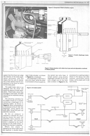
Where two means of operating the same brake shoes are required, a double diaph
ragm brake actuator, as shown in Figure 4, is employed.
One diaphragm is fed from a side entry boss, while the other is connected to the air supply by the central rear entry boss. A simple system using double diaphragm cylinders at the rear and a single one on the front axle is shown in Figure 5. (No provisions for a parking brake shown in this layout, but othei systems, particularly sprinc brakes, will be dealt with in thE next article).