


IMPROVED PROPELLER SHAFT ASSEMBLY QILENCE during running and a degree
Page 80
If you've noticed an error in this article please click here to report it so we can fix it.
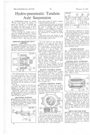
of torsional flexibility are claimed for an improved propeller shaft shown in patent No. 857,420. (Layeock Engineering, Ltd., Victoria Works. Sheffield, 8.) The drawing, shows the rearmost end of a typical propeller shaft. The flange (1) of the output yoke, instead of being attached directly to the driven member
(2) is fixed to an inner, metal cup (3). The driven member carries a larger cup (4) and the two are joined by a rubber sleeve (5).
The sleeve is bonded to the inner cup and drives the outer one by friction, sufficient of which is created by precompressing the rubber before assembly.
Should the rubber fail, a temporary driving connection will he provided by the engagement of the heads of the two rings of bolts (6 and 7).
OIL-ENGINE STARTING
PAT EN T No. 857,293 shows a fitment for introducing ether or other volatile liquid into the air intake of an oil engine to improve starting. (J. Drake; 6 The Hornet. Chichester, Sussex.)
The unit shown in the drawing is mounted in the cab, the body having attached to it a small-bore pipe (1) leading to the intake. On the driver's side is a rubber-bushed receiving socket for the nozzle of a can of liquid. The volatile liquid is contained in one of the modern aerosol packs under pressure.
To operate, a spring-loaded lever (2) is pushed downwards, and the nose (3) of the aerosol can inserted into the socket. Upward pressure on the can opens its valve, and liquid is introduced into the engine intake. This is done while the starter is operating.
When the can is removed the !ever returns fo its original position, and the plug (4) seals the unit to prevent foreign matter being drawn into the intake.
SEALING UNIVERSAL JOINTS
PATENT No. 858,436 shows a means of retaining lubricant in a Hooke's type universal joint. The scheme uses an 0-ring between each journal peg and its surrounding bore in the yoke member. The patent comes from Birfield Engineering, Ltd_, Stratford House, Stratford Place, London, W.I.
VARYING INJECTION TIMING
PATENT No. 857,295 shows an injection pump in which the timing is automatically varied to suit the prevailing load conditions, (V. Roosa, 1699 Boulevard, West Hartford. Conn.. U.S.A.)
The drawing shows the operative par of the pump. A pair of opposed plungers (1) create a pumping space between them as they revolve inside a cam-ring (2) having four lobes. The pump output is then directed to a rotary distributor. The drawing shows the pivot at th end of the rocking beam (1), which i attached through a rubber bush (2) t the ends (3) of lugs from the axle tube.
Normally, these parts are united b! a straight-through pin, but in this cas a pair of separate plugs (4 and 5) an employed. Their short length make them unlikely to seize and even if the do, it is less difficult to remove them They are held in position by a centra bolt (6).
DRIVE FOR TYRE PUMP ATENT No. 854,236 (Veh Schlepper werke Nordhausen, 30c Frei-vom Stein-Strasse, Nordhausen, Germany shows a tyre pump mounted on the ski' of the gearbox and operated by a clutch able eccentric inside the box. The chic advantage is that there is no acfditiona lubrication problem