


A High-reduction Axle Assembly
Page 28
If you've noticed an error in this article please click here to report it so we can fix it.
THE higher the reduction on a driving axle, the lighter can the shafts be, and a design in which the light shafts arc extended as far as the • wheel hubs is shown in patent No. 741,170 (F. Cowell and Kirkstall Forge Engineering, Ltd., Kirkstall
Forge, Leeds, 5).
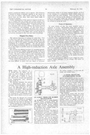
The drawing illustrates the scheme in a diagrammatic form. A conventional bevel-crownwheel reduction (1) is first used and drives the halfshafts; the differential gear is incorporated at this point. Each half-shaft terminates in a pinion (2) which drives a number of planet gears (3). These are mounted on a free-running carrier, the inner end of which is cut as a gear (4).
This forms the sun-gear of a second set of planets (5) which are journalled on fixed pins on the axle-casing. They transmit the final drive to the hub via a toothed annulus (6) formed inside it.
The overall reduction obtained from this arrangement is 13 to 1. AN EASILY PRODUCED RUBBER SHACKLE-BUSH
ARUBBER bush for spring shackles and similar purposes forms the subject of patent No. 741,579 (L. Thiry, 104 South Franklin Street, Chagrin Falls, Ohio, U.S.A.). The bush is made by moulding and -is bonded neither to the pin nor to the sleeve.
The drawing shows at 1 the shape of the bush before assembly. It is tapered both internally and externally, a feature that considerably simplifies moulding.
In assembly, as shown at 2, it is slid over a parallel pin and is distorted thereby into parallelism on the outside. The application of the nut and plate squeezes up an end flange (3) and the resulting compression flows throughout the rubber, causing it to grip both the inside and outside faces.
A NOVEL MEANS FOR SYNCHRONIZING GEARS
SYNCHRONIZING devices for gearboxes usually employ some form of friction cones, but in a large gearbox these, too, tend to become large and expensive if heavy wear is to be avoided. A novel scheme in which the gear elements are accelerated by a jet of oil, is shown in patent No. 741,264 ( Bucssing Nutzkraftwagen G.m.b.H., 40 Heinrich Buessing-Strasse, Braunschweig, Germany).
The drawing shows only the basic principle, no details being given of the actual construction. The large layshaft gear is cut into the form of a turbine wheel (I) against which is directed an oil jet (2). The jet is controlled by a valve (3) so attached to the gear lever that it is brought into operation when changing gear.