


Improved Vacuum Brake for Oil-engined Vehicles
Page 62
If you've noticed an error in this article please click here to report it so we can fix it.
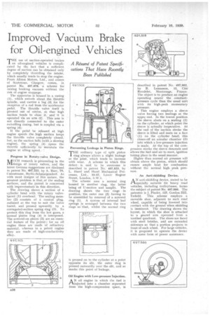
THE use of suction-operated brakes on oil-engined vehicles is complicated by the fact that a sufficient degree of suction can be obtained only by completely throttling the intake, which usually tends to stop the engine. From Albion Motors, Ltd., and others of Scotstoun, ' Glasgow, comes, in patent No. 497,878, a scheme for raising braking vacuum without the risk of engine stoppage.
The apparatus is housed in a casing (1), which swivels about the throttle Spindle, and carries a lug. (3) ,fdr the reception of a rod from the accelerator pedal.. The throttle valve itself is pivoted out of centre, .sb that high suction tends to cicise it, • and ' it is operated via an arm .(2). . This arm is not directly connected to the -outer swivelling casing, but is coupled via a
spring (4); .
It the pedal be released. at high engine speeds the .hig.1) suction keeps the throttle valve completely :closed, but, as the suction falls (with a slowing engine), the spring (4) cipens the throttle sufficiently' to'maintain the engine at idling :speed.
progress in Rotary-valve Design.
MUCH research is :proceeding in the design of 'rotary valves,: and the latest German suggestions are disclosed in patent No, 497,523, by A. 'Baer, 70, Cunostrasse, Berlim•Schmargendorf. As with most designs' of this nature, the greatest problem is that of the sealing surfaces, and the daten't is concerned with improvements in this direction, The .drawing shows a section of a cylinder head with the rotary valvebarrel (1) overhead: The sealing member (2) consists of a conical plug, radiused at the top to suit the valve barrel, and Dressed upwardly by a corrugated-section spring ring (3). To protect this ring from the hot gases, a normal 'piston ring (4) is interposed. The screwed-on pieces (5) arc an essential feature of the patent ; for an oil engine these are made of refractory material, whereas in a petrol engine they are made of high-conductivity alloy.
Preventing Leakage in Piston Rings.
THE ordinary type of split piston ring always allows a slight leakage at the joint, which tends to increase with wear. A scheme in which this defect, is said to be overcome is described in patent No. 497,823, by L. Hard l and Hard l Mechanical Processes, Ltd., 33-37, Lower Regent
Street, London, SAVA. • The scheme uses a normal ring houBed in another ring, the latter being of IT-section and unsplit. The drawing shows the two rings in position, the outer one (2) having to he a'ssetriblecl by removal of a screwed ring (1). A system of internal leaf springs is arranged between the two rings so that, whilst the normal ring described in patent No. 497,902, by R. Lemasson, 12, Cite Rondelet, Montrouge, France. The object is to produce an engine operating nearer the constantpressure cycle than the usual unit with its high-peak momentary pressure.
This engine employs a sleeve valve having two Beatings at the upper end. In the lowest position the sleeve abuts on a seating (2) on the cylinder, at which point the Sleeve is actually inoperative. At the end of the suction Stroke the sleeve is lifted and seats on a face ' (1) on the cylinder head; this closes-off an annular chamber (3) into which a low-pressure injection is made: At the top of the compression stroke the sleeve descends and allows the fuel and air to meet, ignition taking place in the usual Manner.
Higher than normal air pressure will obtain above the piston, which should ensure ample heat for combustion without the normal high. peak pressure.
An Anti-skidding Device.
AN anti-skidding device, stated to be speCially suitable fOr heavy road vehicles, including trolleybuses, forms the subject of patent No. 497,886. The patentee is J. Pinder, 127, Gordon Hill,
Enfield. This . scheme employs a movable shoe, adjacent to each road wheel, capable of being lowered into contact with the ground when skidding is imminent. The drawing shows the layout, in which the shoe is attached to a geared arm operated from a toothed quadrant. The shoes are faced with Steel bristles, and are extended sideways so that a portion projects in front of each wheel. For large vehicles, it is proposed to operate the device with some form of power assistance,