 1
1 2
2 3
3 4
4 5
5 6
6 7
7 8
8 9
9 10
10 11
11 12
12 13
13 14
14 15
15 16
16 17
17 18
18 19
19 20
20 21
21 22
22 23
23 24
24 25
25 26
26 27
27 28
28 29
29 30
30 31
31 32
32 33
33 34
34 35
35 36
36 37
37 38
38 39
39 40
40 41
41 42
42 43
43 44
44 45
45 46
46 47
47 48
48 49
49 50
50 51
51 52
52 53
53 54
54 55
55 56
56 57
57 58
58 59
59 60
60 61
61 62
62 63
63 64
64 65
65 66
66 67
67 68
68 69
69 70
70 71
71 72
72 73
73 74
74 75
75 76
76 77
77 78
78 79
79 80
80 81
81 82
82 83
83 84
84 85
85 86
86 87
87 88
88 89
89 90
90 91
91 92
92 93
93 94
94 95
95 96
96 97
97 98
98 99
99 100
100 101
101 102
102 103
103 104
104 105
105 106
106 107
107 108
108 109
109 110
110 111
111 112
112 113
113 114
114 115
115 116
116 117
117 118
118 119
119 120
120 121
121 122
122 123
123 124
124 125
125 126
126 127
127 128
128 129
129 130
130 131
131 132
132 133
133 134
134 135
135 136
136 137
137 138
138 139
139 140
140 141
141 142
142 143
143 144
144 145
145 146
146 147
147 148
148 149
149 150
150 151
151 152
152 153
153 154
154 155
155 156
156 157
157 158
158 159
159 160
160 161
161 162
162 163
163 164
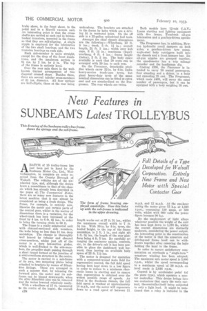
164 New Features in SUNBEAM'S Latest TROLLEYBUS This drawing of the Sunbeam trolley-bus frame. shows the springs and the sub-frame.
Page 88
Page 89
If you've noticed an error in this article please click here to report it so we can fix it.
ABATCH. of 15 trolley-buses has just been put in hand by the Sunbeam Motor Co., Ltd., Wolverhampton, to complete an order received from the County Borough of Walsall. The vehicles are of the sixwheeled type, and, although the design bears a resemblance to that of the chassis which has already been described in the pages of; The Commercial Motor, there are so manynew features in the latest machine that it can almost be considered as being a fresh design. The frame, for example, is entirely new, likewise the motor and certain parts of the control gear, whilst in the matter of dimensions there is a variation, for the wheel-track has been increased at the front by 4 ins. to 6 ft. 41 ins., in order to bring the turning circle to 60 ft.
The frame is a really substantial unit with channel-sectioned side members, the webs being no less than 11 ins, deep amidships. The chassis is thoroughly well braced by tubular and channel cross-members, whilst just aft of the motor is a deep box-section girder, which is well-flitehed th the side-members, the propeller shaft passing through a short tunnel formed at the junction of a semi-cruciform structure in the centre.
The motor is carried in a sub-frame of its own, two mounting plates being attached to brackets by means of Silentbloc fittings. These are arranged in such a manner that, by releasing the forward pins, the motor and its subframe can be hinged downwards, when the after Silentbloc pins can be removed and the motor lowered relatively easily. With a wheelbase of 17 ft. (measured to the centre of the bogie), the overall
c3S length works out at 27 ft. 54 ins., whilst the maximum overall width is 7 ft. 54 ins. With 36-in. by 8-in. tyres, the loaded height, to the top of the frame amidships, is 2 ft. 1 in., and right aft 1 ft. 5/ ins., the length of the rear platform being 4 ft. 5 ins. By carefully arranging the contactor panels, controls, etc., in the driver's cab it has been possible to place the dashboard well forward, thus leaving an available body space of 23 ft. 114 ins.
The motor is designed for operation with a compound-wound main field for regenerative control, the full field speed having been kept down to a low figure in order to reduce to a minimum rheostatic losses in starting_ and to ensure that regeneration is obtained over the widest possible range of speeds. As fitted in the Sunbeam chassis, the full field speed is reached at approximately 10 m.p.h., and the motor will regenerate down to a road speed of between 11 m.p.h. and 12 m.p.h. At the one-hour rating the motor gives 75 h.p. at 1,020 r.p.m., consuming 130 amps. at 500 volts, whilst with 600 volts the power figure becomes 90 h.p.
By the employment of light alloys wherever possible the weight of the unit has been kept down to 1,170 lb., whilst the overall dimensions are distinctly moderate, considering the power output, An interesting point in the construction of the motor is that the armature and driving-end frame head can be withdrawn together after removing the bolts holding the head to the frame.
In order to ensure satisfactory commutation on overloads a " single-turn " armature winding has been adopted. The maximum safe motor speed is 3,000 r.p.m., whilst the speed corresponding to a maximum speed of 30 m.p.h. on level roads is 2,646 r.p.m.
Control is by accelerator pedal (of the plate type), which operates a master controller. This device brings into use contactors that carry the main current, the controller itself being subjected to only a light load. It might be mentioned that a relay is included in the shunt field, and, should the regenerative voltage exceed that of the line, the relay inserts a resistance in the lighting circuit preventing a lamp "burn out."
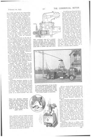
A new type of silently operating contactor has been evolved, the whole secret lying in the simple fact that the movement of the armature tail is limited by rubber buttons. The only sound that emanates from the whole arrangement is the slight click when the actual contactor tips are brought together (these tips, by the way, are of silver, so as to reduce" arcing "). There are, of course, two single-pole automatic circuit breakers of the traction type located in the driver's cab, whilst a negative rail skate and cable, with an insulated brindle are supplied.
Resistances are housed on the side of the main frame, and great care has been, taken to ensure proper ventilation and adequate shielding from the saloon bodywork. The element is wire wound, restless and jointless, a large steel shield, together with a steel stoneguard, being mounted underneath to protect the grids from loose metal thrown up by the wheel < All the electrical gear has been supplied by the British ThomsonHouston Co., Ltd., of Rugby.
The transmission follows the lines of the existing Sunbeam trolley-bus, but the diameter of the propeller shaft has been increased from 3 ins. to 4 ins., in order to cope with the higher torque of the motor and to make perfectly certain that "whirling" does not occur.
Another new chassis feature is the lubrication system, grouped grease nipples being provided at all important points. There is, for example, a box inside the driver'i cab equipped with ten grease nipples, providing lubrication to such items as the shacklepins, spring pins, the foot-brake pedal, the handbrake lever, steering connections, etc. Both rear axles are of the underslungworm type, the differentials being each composed of four planets and two sun wheels.
Particular attention attaches to the braking system, which, although not absolutely now on the particular chassis under review, has not before been described in detail. The pedal-applied system incorporates a Sunbeam design of patent master-cylinder control for operating expanding shoes of the Lockheed type. This control gear is composed of a master-cylinder box with These two sketches indicate how a new form of silent-acting contactor gear has been obtained, the main feature being to limit by means of rubber buttons the movement of the armature tail. This arrangemeat is clearly shown in the
upper sketch.
three cylinders, each of which actuates the brakes on each axle, whilst an outer casing acts as a reserve tank by which the system is maintained full of fluid. Each cylinder is 11, ins, in diameter and has a compensation device (patented by the Sunbeam concern), which has an additional attraction in that, in the unlikely event of a pipeline breaking, only one system .(of three) is affected.
As will-be seen from the drawing reproduced, there are threo rubber cups and three needle valves, one of each per cylinder. Pressure is generated in the master cylinders by depressing the pedal, when the rubber cups are lifted, allowing the needle valves to be unseated—an operation which puts all the master cylinders in communication with each other, and thus compensates for any unequal displacement which may exist. It is obvious that with a broken pipe the cylinder affected would offer no resistance, so that the rubber cup would not lift and the strong coil spring provided would keep the needle valve on its seat, thus sealing the remaining two cylinders and ensuring a good brake on their corresponding axles. In any public-service vehicle this is, of course, a most important feature, and one that affords, in the event of a failure, a valuable safety measure.
All four wheels of the rear bogie have malleable cast-iron brake drums of 19f ins, diameter, with provision for shoes 4 ins. wide. The front drums are 161 ins. in diameter and the shoes are 31 ins. wide ; these, like the shoes at the rear, are lined with Perodo material in. thick, so that a very long life, before re-facing becomes necessary, is assured.
The brake-shoe actuation employs the normal Lockheed system, pressure cylinders 2 ins. in diameter being mounted on the brake-shoe carrier brackets; they expand the shoes by means of short push-rods. There is a total area of 884 sq. ins, of friction material in contact with the drums when the footbrake pedal is applied. A powerful hand brake is available in case of enaergency. It is of the pull-on type and is linked up to the rear shoes by means of toggle levers mounted on the shoecarrier brackets. It is thus seen that the whole of the brake equipment has been accorded particularly thorough attention.
Altogether this is a robust, welldesigned and splendidly finished chassis, which 'should give excellent service for long periods without need for overhaul.