 1
1 2
2 3
3 4
4 5
5 6
6 7
7 8
8 9
9 10
10 11
11 12
12 13
13 14
14 15
15 16
16 17
17 18
18 19
19 20
20 21
21 22
22 23
23 24
24 25
25 26
26 27
27 28
28 29
29 30
30 31
31 32
32 33
33 34
34 35
35 36
36 37
37 38
38 39
39 40
40 41
41 42
42 43
43 44
44 45
45 46
46 47
47 48
48 49
49 50
50 51
51 52
52 53
53 54
54 55
55 56
56 57
57 58
58 59
59 60
60 61
61 62
62 63
63 64
64 65
65 66
66 67
67 68
68 69
69 70
70 71
71 72
72 73
73 74
74 75
75 76
76 77
77 78
78 79
79 80
80 81
81 82
82 83
83 84
84 85
85 86
86 87
87 88
88 89
89 90
90 91
91 92
92 93
93 94
94 95
95 96
96 97
97 98
98 99
99 100
100 101
101 102
102 103
103 104
104 105
105 106
106 107
107 108
108 109
109 110
110 111
111 112
112 113
113 114
114 115
115 116
116 117
117 118
118 119
119 120
120 121
121 122
122 123
123 124
124 125
125 126
126 127
127 128
128 129
129 130
130 131
131 132
132 133
133 134
134 135
135 136
136 137
137 138
138 139
139 140
140 141
141 142
142 143
143 144
144 145
145 146
146 147
147 148
148 149
149 150
150 151
151 152
152 153
153 154
154 155
155 156
156 157
157 158
158 159
159 160
160 161
161 162
162 163
163 164
164 165
165 166
166 167
167 168
168 169
169 170
170 171
171 172
172 173
173 174
174 175
175 176
176 177
177 178
178 179
179 180
180 181
181 182
182 183
183 184
184 185
185 186
186 187
187 188
188 Improving the Safety of Engine Lubrication
Page 138
If you've noticed an error in this article please click here to report it so we can fix it.
THE specification of Morris Commercial Cars, Ltd., and W. W. Hamill, No. 340,700, points out that owing to vibration it is not unknown for the pipe leading to the oil-pressure indicator to break, in which case there is a probability of the whole of the oil escaping and causing serious damage to the engine.
The present invention provides a means whereby, should such a breakage occur, the ball shown, which normally lies in the lower position, will be raised by the pressure of the oil and will stop its flow when it meets the seating above it.
The only effect of a breakage of this pipe would then be to throw the indicator out of action, but the oil would still be retained and circulated.
Pressure-fed Lubrication to Steering Ball Joints.
AN arrangement for feeding oil under pressure to tha ball joints of steering gears is described in patent No. 340,694, by B. I. Day, Cloverfield, West Wittering, Chichester.
A pipe (A) is described as being sweated to the steering arm and leading to a radial hole in the stem of the ball, from whence it rises to the two radial outlets in the ball, where it meets the bearing surfaces. The hole is plugged at the top.
The most difficult part of the problem, however, the leading of oil from a pressure system to a moving steering arm, Is not made clear. Sometimes arrangements are made for rigid pipe lines terminating in flexible tubing, but this would be a somewhat complicated method in this ease.
A New Tappet-clearance Adjustment.
IN patent No. 340,591 Morris Commer cial Cars, Ltd., W. W. Hamill and C. K. Edwards describe a screw adjustment on the end of the valve stem which can be used as a means for adjusting the clearance between it and the tappet.
The stem is threaded at its end and a cap nut is provided with an extending sleeve which is conical on its outer side and is split up so that it can be campressed to cause it to grip the valve stem.
The washer against which the spring bears is coned, so that the pressure of the spring should cause it to compress the split parts of the nut. A keyway is formed in the stem to prevent the washer from rotary movement relative to the stem.
A special tool is provided with which the washer can be depressed so that it disengages itself from the nut while the latter is being adjusted, the tool having pins which engage with holes in the washer to prevent rotary movement of the latter while the nut is being turned.
Many users of such vehicles do not favour the employment of any kind of special tool for any purpose, as such tools often get lost, and in the present instance the adjustment of the clearance would not be an easy matter should tho special tool not be to hand, although such work is usually carried out in the garage.
A Ticket-stamping and Indicating Device.
THE ticket-stamping device described inpatent No. 340,028, by G. W. Allison, 157, Boundary Road, Hoe Street, Layton, E,, is of the kind in which a ticket is inserted in a slot (5), and by pressing a knob (6) the necessary particulars are printed on it.
The device carries with it a clock so that the time of day can be printed on the ticket. The milled disc (4) sets the printing mechanism to the class and amount of the fare.
A carbon strip between the ticket and the printing type keeps a record, or a counter can be used.
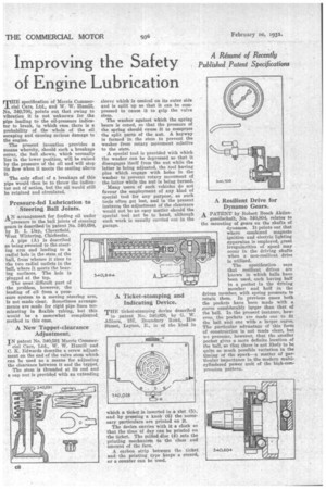
Resilient Drive for Dynamo Gears.
A PATENT by Robert Bosch Aktien
gesellschaft, No. 340,804, relates to the mounting of gears on the shafts of dynamos. It points out that where combined magneto ignition and electric lighting apparatus is employed, great irregularities of speed may occur in the driving shafts when a non-resilient drive is utilized.
The specification says that resilient drives are known in which balls have been used, each having half in a pocket in the driving member and half in the driven member, with spring pressure to retain them. In previous cases both the pockets have been made with a curve considerably larger than that of the ball. In the present instance, however, the pockets are made one to fit the ball and one with a larger curve. The particular advantage of this form of construction is not made clear, but we presume, however, that the smaller pocket gives a more definite location of the ball, so that there is not likely to be quite so much possible variation in the timing of the spark—a matter of particular importance in the modern multicylindered power unft of the high-compression pattern,