


Patents Completed.
Page 20
If you've noticed an error in this article please click here to report it so we can fix it.
Complete specifications of the following patents will be sent to any address in the United Kingdom upon receipt of eightpence per copy at the Sale Branch, Patent Office, Holborn, W.C.
NON-SKID DEVICE.—Ogilvie.—No. 545, dated 8th January, 1909.—This device comprises a roller yieldingly supported from the back axle by suitable hangers, which are designed' to take lateral strains. The roller is provided with a spherical hub, which engages a spherical portion provided on its supporting axle. The spherical hub or nave is flared outwardly at each side, so as to permit the roller to be tilted. The axle supporting the roller is mounted so as to be slidable in the hanger brackets, and the roller is yieldingly held in contact with the ground by means of spiral springs. The roller is provided with an indiarubber tire which normally makes contact with the ground, and its edges arc chamfered so as to present a sharp edge to the ground when the roller is tilted. On the vehicle slipping laterally, the roller will be tilted so that one of its edges will be forced into the ground. The degree of inclination which the roller may assume is limited by castors carried by the hanger brackets. These castors permit the roller to rotate, notwithstanding that it is forced into contact with the ground. Thus it will be seen that, although the vehicle is prevented from slipping sideways, this device offers no resistance to forward movement of the vehicle.
FLASII BOILER.—Crompton. — No. 28,521, dated 31st December, 1908.—The object of this invention is to arrange the tubes in a compact and self-supporting form while, at the same time, affording the maximum heating surface. The tubes are formed into helical coils, the pitch of which is double tho external diameter of the tubes, so that each coil may be interlaced and grouped to
gether. The feed water entering the generator at the top traverses a helical descending path, so that the lower half of each turn of the helix will always contain water which is trapped therein. It will, therefore' be seen that the water cannot descend by gravity so as to empty the generator completely, for the lower half of each coil can only be emptied by the waters being evaporated or blown off under pressure.
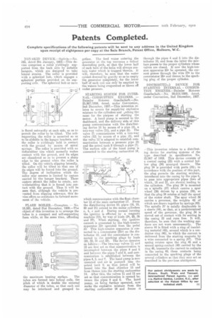
STARTING SYSTEM FOR INTERNAL COMBUSTION ENGINES. — Daimler Motoren Gesellschaft.—No. 25,967/1908, dated. under. Convention, 2nd December, 1907.—This invention relates to means for supplying explosive mixture to the cylinders and 8niting the same for the purpose of starting the motor. A hand pump is secured to the dashboard, and the delivery side of this pump communicates with the distributing device 10 by means of a pipe (4), a two-way valve (11), and a pipe (6). The valve 11 communicates with a two-way valve (12) by means of a pipe (5), and the valve 12 is adapted to establish communication between a pressure pipe (8) and the petrol tank 9 through a pipe (7). The auction side of the hand pump is connected to the starting carburetter 14, which communicates with the float chamber 15 of the main carburetter 17. From the distributing device 10, pipes (18, 19, 20 and 21) extend to the motor cylinders a, b, c and d. During normal running the ignition is effected by a magneto machine (23). by way of leads (24, 25, 26 and 27). When starting, the ignition current is generated by the high-tension apparatus 25a operated from the pedal 50. This high-tension apparatus is connected to a commutator (26a) on the distributor 10, and the commutator is connected to the sparking plugs by leads (29, 30, 31 and 32). The device operates as follows :—The two-way valves 11 and 12 are first set so that communication is interrupted between the pipes 4 and 6 and between the pipes 7 and 8, and communication is established between the pipes 4, 5, and 7. The hand pump is now operated and air is pumped into the petrol tank 9. so that petrol will be forced into the float chamber 15 and from thence into the starting carburetter 14. After this, the valves 11 and 12 are set so that communication is opened between the pipes 4 and 6. The hand pump, on being further operated, now sucks the explosive mixture from the starting carburetter 14 and forces it
through the pipes 4 and 6 into the distributor 10, and from the latter the mixture passes to the proper cylinders whose valves are closed. If now the high-tension apparatus 25a be operated, the current passes through the wire 27a to the commutator 26a and thence to the sparking plug of the proper cylinder.
DISTRIBUTIN VI DEVICE FOR STARTING INTERNAL COMBUSTION ENGINES.—Daimler Motoren Gesellschaft.—No. 29,615/1909, dated, under Convention, 2nd December, 1907.
—This invention relates to a distributing device for starting systems of the type described in specification No. 25,967 of 1908. This device consists of a conical casing (33) with a conical hollow plug (34) arranged therein. The plug 34 is provided with ports (35); in accordance with the position of this part, the plug permits the starting mixture, introduced into the casing by the pipe 6, to pass into appropriate pipes (two of which, 18 and 21, are shown) leading to the cylinders. The plug 34 is mounted on a spindle (37) which carries a spur wheel (38) driven by a pinion (39), so that the plug 34 rotates at half the speed of the motor shaft. The spur wheel 38 carries a governor, the weights 42 of which are drawn together by springs (43). The spindle 37 is axially displacable in a sleeve (44), so that, at a predetermined speed of the governor, the plug 34 is moved out of contact with its seating in the casing 33 and runs free. It will, therefore, be seen that the working surfaces are not worn unnecessarily. The sleeve 44 is fitted with a ring of insulating material (45), around which is a condnctor ring (46), to which the current is delivered from the starting magneto by a wire connected to a spring (47). This spring rotates upon the ring 46 and a second spring-contact (48) carried by the ring 46, transmits the current to contacts in the casing 49, these contacts being connected to the sparking plugs of the several cylinders so that they may act as described in the previous abridgment.