


Contributions from Drivers and Mechanics.
Page 19
If you've noticed an error in this article please click here to report it so we can fix it.
TEN SHILLINGS WEEKLY for the Best Communication Received, and One Penny a Line of ten words for any thing else published.
Drivers of commercial-motor vehicles and tractors, and mechanics and jorenren of garages or shops, are invited to send short contributions on any subject wnich is likely to prove of interest to our readers. Workshop tips and smart repairs ; long and successful runs ; interesting Photographs : all are suitable subjects. Send a post-card, or a letter. or a sketch to us—no matter how snort, or how written, or how worded. We will "knock it into shape" and prepare sketches, where necessary, before publication. The absence of a sketch does not disqualify for a price. When writing use one side of the paper only and mention your employer's name as a guarantee of bona fides. Neither your own nor your employer's name will be disclosed. Payment will be made immediately after publication. Address your letters to The Editor, THE COMMERCIAL MOTOR, 7-75, Rosebery Avenue, London, E.C.
The writer of a contribution which was signed " (Flintshire) omitted to attach his full name and postal ad(.ress. In the absence of the particulars, the letter was inadvertently destroyed. As the matters described were of some interest, if the writer cares to furnish another copy of •his letter, with the proper identification particulars attached, we will corsider it favourably.
Yearly Bonuses for Contributors.
In order further to encourage the readers of our "Drivers and Meohanies " pages to send to us, regularly, suitable practical contributions, we have decided to offer two additional prizes each year, in the following form :—
A bonus of two guineas to the contributor who succeeds in securing the weekly ten-shilling prize for the largest number of times during the twelve months ending 1st December, 1910.
A bonus of one guinea to the contributor who has the largest num her of individual contributions inserted during the twelve months ending let December, 1910.
Joining a Driving Chain Anothek Device.
The sender of the model described herewith hos been awarded the 10s. prize this week.
[6591 " R.W." (Durham) has sent to us a roughly-made wooden model of a clever idea for an appliance for drawing together the two ends of a driving chain, when it is
desired to insert the coupling pin or bolt. This and several descriptions of other interesting devices for the same purpose have reached us as a result of our publication and illustration, recently, of other similar useful schemes [Letters No. 640, 630 and 6l31. We shall insert contributions about some others of these chain-jointing " dodges " as occasion offers. Had it been convenient, we should have liked to have reproduced a photograph of the original model which was sent to us in this instance, as a praetical illustration of our readiness, at all times, to consider contributions about suitable ideas, however roughly they may be presented to us. Providing the device or experience be interesting, we are always prepared to take a lot of trouble with such communications, in order to " knock them into shape," by rewriting the description, if necessary, and by preparing proper drawings by way of illustration. In the present instance, our contributor, " It .W.,'' prepared, with the rough material which he had at his command, a model made of cardboard strips and bits of wood, and, we must admit, that this was none too easy to understand. No description of the model was attached. It, however, in all its crudeness, represented an ingenious contrivance, and, therefore, we had the contribution " polished up " by the preparation of a suitab1:2 drawing and of a short description
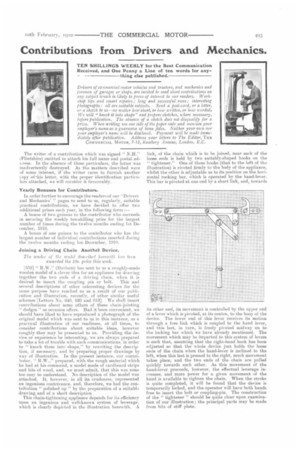
This chain-tightening appliance depends for its efficiency upon an ingenious and well-known system of leverage, which is clearly depicted in the illustration herewith. A link, of the chain whiCh is to be joined, near each of the loose ends is held by two suitably-shaped hooks on the " tightener." One of these hooks (that to the left of the illustration) is riveted firmly to the body of the appliance, whilst the other is adjustable as to its position on the horizontal rocking bar, which is operated by the hand-lever. This bar is pivoted at one end by a short link, and, towards
its other end, its inurement is controlled by the upper end of a lever which is pivoted, at its centre, to the body of the device. The lower end of this lever receives its motion through a free link which is coupled to the hand lever, and this last, in. turn, is freely pivoted midway on to the locking bar which we have already mentioned. The movement which may be imparted to this system of levers is such that, assuming that the right-hand hook has been adjusted so that the whole device just holds the loose ends of the chain when the hand-lever is inclined to the left, when this last is pressed to the right, much movement takes place, and the two ends of the chain are pulled quickly towards each other. As this movement of the hand-lever proceeds, however, the effectual leverage increases, and more power for a given movement of the hand is available to tighten the chain. When the stroke is quite completed, it, will he found that the device is temporarily locked, and the operator will have both bands free to insert the bolt or coupling-pin. The construction of the " tightener " should be quite clear upon examination of our illustration: the principal parts may be made from bits of stiff plate.