


Mixed Loads Artic Car Carrier
Page 60
Page 61
If you've noticed an error in this article please click here to report it so we can fix it.
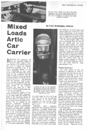
BECAUSE new regulations will limit the maximum length of draw-bar trailer outfits to 59 ft. from January 1, car carriers based on this type of vehicle are virtually obsolescent, according to Mr. A. H. Carter, managing director of the Carter Engineering Co. Ltd., Tamworth, as they will reduce the overall length by 6 ft. compared with the length of outfits in current use and the maximum number of cars that can be carried from 12 to 7. The draw-bar trailer has, therefore, "had its day" as an economic proposition and Mr. Carter has developed an articulated outfit, known as the Carveyor Universal that caters for a wide variety of vehicles, including light vans of up to 1 ton capacity.
An all-important feature of the vehicle is the use of rubber suspension for the bogie which has enabled the height of the drop-frame section of the lower deck to be reduced to 2 ft., and of equal interest the brakes of the forward axle are applied by an imported Anchorlok double-diaphragm unit through a compensated mechanical linkage which provides automatic and progressive operation of the brakes by spring action in the event of an air-pressure deficiency. Spring brakes of various types will in due course be manufactured by an associated company, the Tamworth Brake Co. Ltd., of the same address.
The Universal has an unladen weight of 3 tons 11 cwt. and is designed for 18-ton-gross applications. Having an overall length of 42 ft. 6 in. it can carry four cars on the top deck and three vehicles on the lower deck, including two vans having overall heights of up to 7 ft. 1 in. and lengths up to 15 ft.
Employing rubber suspension offered the only exploitable means of obtaining a low-height bottom deck and its use followed successful applications to single-deck transporters, the first application about 12 months ago being to a close-coupled two-car trailer having an unladen weight of 191 cwt. and a maximum laden weight of 4 tons. Fitted in place of a balancebeam type of leaf-spring suspension, advantages of the rubber type include the elimination of spring failure and wear (a high rate of wear was a particular disadvantage of the balancebeam mechanism), a substantial reduction in weight and an improved ride when the vehicle is travelling unladen.
On the close-coupled outfits, each axle is underslung from the ends of the 2-ft. trailing arms and Aeon 1525/65 rubber springs are located above the axle between the ends of the arms and the frame members. The springs act in compression and rebound is limited by check chains. Some 150 vehicles have been equipped with this form of suspension and the total absence of chain breakage confirms Mr. Carter's claim that the springs control rebound as well as bump. Static laden deflection is about tin., the bump deflection being approximately 11 in.
Rubber Resistance
Mr. Carter points out that the resistance to deflection of rubber in compression increases with the rate of application (according to the Shore hardness) and that this affords a substantially constant-periodicity characteristic. None of the Carter systems is fitted with shock-absorbers.
The suspension of the prototype of the latest seven-vehicle artic is also based on Aeon 1525/65 rubber springs (in this case pre-tensioned) of which four are fitted to each axle. Suspended in the channels of the inverted channelsection main-frame members, the springs are attached to fabricated brackets on the axle by means of bolts that pass through the centre of the springs which are compressed upwards, the frame members being sufficiently robust to obviate bending between the axles, which would reduce transference of a part of the load to the springs of the second axle.
The static deflection of the 1525/65 springs is 14 in., the bump deflection being rather more than 2-.1 in. The load rating of each spring is 20,000 lb.
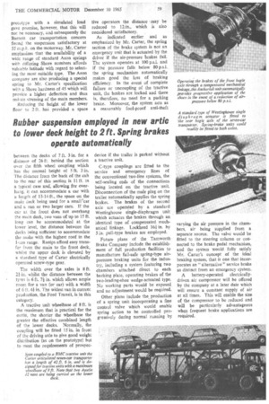
Detailed modifications will be made to the system as dictated by experience, which may include the insertion of disc type metal springs between the bracket and the channel member to control rebound. Operation of the prototype with a simulated load gave promise, however, that this will not be necessary, and subsequently the Barnett car transportation concern found the suspension satisfactory at 55 m.p.h. on the motorway. Mr. Carter emphasizes that the availability of a wide range of standard Aeon springs with differing Shore numbers affords valuable latitude with regard to selecting the most suitable type. The Aeon company are also producing a special spring to Mr. Carter's specification with a Shore hardness of 45 which will provide a higher deflection and thus reduce stressing of the main members.
Reducing the heigbt of the lower floor to 2 ft. has provided a space tive operators the distance • may be reduced to 12in., which is also considered satisfactory.
As indicated earlier and as emphasized by Mr. Carter, the spring section of the brake system is not an emergency unit that is actuated by the driver if the air-pressure brakes fail. The system operates at 100 p.s.i. and if the pressure falls below 80 p.s.i. the spring mechanism automatically makes good the loss of braking efficiency. In the event of complete failure or uncoupling of the tractive unit, the brakes are locked and there is, therefore, no need for a parking brake. Moreover, the system acts as a reasonably fool-proof anti-theft Operating the brakes of the front bogie axle through a compensated mechanical linkage, the Anchorlok unit automatically provides progressive application of the shoes in the event of a reduction of air
pressure below 80