


Servooperated Clutch Mechanism
Page 28
If you've noticed an error in this article please click here to report it so we can fix it.
A Résumé of Patent Specifications that Have Recently Been Published DOWER-ASSISTED clutch operation 1 is a refinement which is more favoured in America than in this country, although some interest is now being shown here. Patent No. 474,420 shows a British design, the patentees being the Pulsometer Engineering Co., Ltd., and R. Warren, both of Reading, Berks. The basic principle is the application of intake suction to a bellows connected to the clutch-operating member. In previous schemes of this nature, the removal of the driver's foot from the accelerator has been sufficient automatically to withdraw the clutch.
Whilst for gear changing this is a convenience, there are times when it may be an embarrassment, and the patent is concerned with a selective valve for use in conjunction with the aiccelerator pedal. The pedal is constructed in the form of a rocking plate, and when operated in the usual manner by toe pressure works only the throttle. To operate the servo valve the pedal is allowed to come to the off position and is then pressed farther backwards with the heel. This opens a valve and connects the clutch-operating bellows with the intake suction.
A Clutch-operated Refinement.
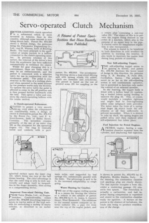
STATED to permit a very smooth ...)take-up, even when the components are considerably worn, a design of clutch is disclosed in patent No. 474,112 by the Rover Co., Ltd., and P. A. Scott-Iversen, both of Helen Street, Coventry. The invention consists primarily of the use of an outer ring (2) as the abutment for the operating fingers (1). The ring is conically bored and contacts with a part
spherical surface upon the inner ring (3), which forms one race of the ball thrust bearing. The chief advantage is that the outer ring is able to rock universally and adapt itself to inequalities in the finger assembly, thus acting as a compensating device.
Improved Four-wheel Driving Unit.
FROM Tatra, Works, Ltd., of PragueSmichov, Czechoslovakia, comes patent No, 474,215 describing improvements in tractor units of the type suitable for embodying a variety of heavy vehicles, as described in an earlier
B46 patent, No. 452,918. The accompanying drawing shows a four-wheel driving unit with sprung wheels (3) added, which are steerable and non-driven. The patent is based on the use of pivoted arms (2) for coupling to the main axles, and supported by leaf springs (1), substantially parallel with the links. The advantage is said to be in the increased adaptability to rough going.
Water Heating for Coaches.
THE use of the engine cooling system as a means for heating the interior of a vehicle is the subject of patent No. 474,232 by C. G. Jones, 1, Garrett Street, West Bromwich. The additions to the normal system comprise an interior radiator (3), a pipe (1) from near the top of the engine jacket, and
a return pipe 'containing a one-way valve (2).• The object of this is to prevent the engine being drained in the .event df a fracture, which also is the . purpose of an upper loop in the pipe. A control valve for temperature regulation is also incorporated.
The scheme is stated to be beneficial in both directions in cold weather—in addition to warming the interior, it also tends to maintain the engine heat during long periods of standing.
New Self-adjusting Tappet.
THE self-adjusting tappet seems to be gaining in favour, and patent No. 473,734 discloses the latest trend of design in this direction, the patentee being A. B. Buckley, 9, Park Hill, Carshalton, Surrey. The scheme 'is novel in so far as the self-adjusting action is not continuously operative, but is permitted to function only under the control of an external member.
In the drawing, the tappet body is fitted with 'a hollow head (1) containing a loaded volute spring tending to unscrew the plug (2). This, of course, would maintain a complete tightness and might lead to over-tightening unless some safeguard were provided. The latter takes the form of a springsteel finger (3) :winch loads the selfadjuster at all time sufficiently to prevent movement. When it is desired to take up slack, the spring fingers are pulled away and then replaced after self-adjustment has taken place.
Fuel Injection for Petrol Engines,
A PETROL engine, having a combustion chamber separate from the cylinder, and employing fuel injection.
is shown in patent No. 472,072 by F.
Boghetto, Reddio Emilia, Italy. In the drawing, the combustion chamber and sparking plug are clearly shown. The fuel injector occupies a bore (2), whilst a restricting passage (1) con nects two spaces. The restriction is actually a carburetter, and fuel injected during compression is vaporized and stored in the combustion chamber ready for ignition. A feature of the patent is the absence of turbulence, the whole aim being to produce stratification of the charge,