


Works Proces:
Page 22
Page 23
Page 24
If you've noticed an error in this article please click here to report it so we can fix it.
at Make for
TRANSMISSIOI NIT EFFICIENCY
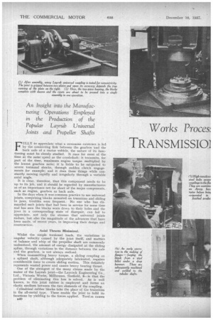
An Insight into the Manufacturing Operations Employed in the Production of the Popular Layrub Universal Joints and Propeller Shafts
Rubber Trunnion Blocks Permit Angular and Axial Movement, Absorb Torsional Shocks and Impulses and
Engender Silent Running
FULLY to appreciate what a strenuous existence is led by the connecting link between the gearbox and the back axle of a motor vehicle, the nature of its functioning must be closely studied. It runs for most of the time at the same speed as the crankshaft; it transmits, for part of the time, maximum engine torque multiplied by the lowest gearbox ratio; it is liable to be subjected to severe torsional shocks, through sudden clutch engagements for example; and it does these things while constantly moving rapidly and irregularly through a variable axial angle.
It is clear, therefore, that this component needs to he up to its job, and it should be regarded by manufacturers as of an importance not far short of the major components, such as engine, gearbox or back axle.
In the days when it was common practice to use universal joints, comprising blocks mounted on trunnions and sliding in jaws, troubles were frequent. • No one who has dismantled such joints that had been in service for some time and has seen the blocks worn down to their holes and the jaws in a corresponding state of disrepair, can fail to appreciate, not only the stresses that universal joints endure, but also the magnitude of the advances that have been made, of recent years, in improving their design and construction.
Axial Thrusts Minimized.
Whilst the simple torsional loads, the variations in angular velocity caused by the joint itself, and matters of balance and whip of the propeller shaft are commonly understood, the amount of energy dissipated at the sliding spline, through variations in the distance between the axle and the gearbox, is not always realized.
' When transmitting heavy torque, a sliding coupling on a splined shaft, although adequately lubricated, requires considerable force to create sliding motion. This definitely represents wasted power and causes heavy bearing thrust.
One of the strongest of the many claims made by the maker of the Layrub joint—the Laycock Engineering Co., Ltd., Victoria Works, Millhouses, Sheffield, 8—is that the problem of eliminating this loss is solved. As is well known, in this joint rubber is employed and forms an elastic medium between the two elements of the coupling.
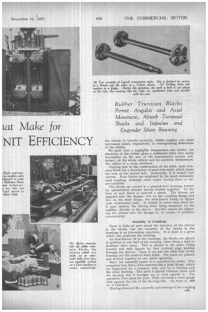
Cylindrical rubber blocks take the place of the trunnions in the all-metal type. These enable the joint to fulfil its functions by yielding to the forces applied. Torsbn causes B40 the blocks to become eccentric, whilst angular and axial movement result, respectively, in correspOnding deflections of the rubber.
No more than a negligible temperature rise results, the elasticity of the rubber gives a cushioned drive that reacts favourably on the rest of the transmission system and, indeed, on the whole vehicle and its contents; furthermore, the rubber is a noise insulator.
Turning now to the construction of the joint, each trunnion block has a foundation of steel-wire mesh, which forms the bore of the central hole. Externally, it is bound with canvas. Four blocks are employed in the most commonly used coupling, although other types, having three or six, are available.
The blocks are carried in a pressed-steel housing, formed by symmetrical circular halves riveted together. In the bore of each block is inserted a sleeve. The sleeves are spigoted into the flanges, two on the coupling flange and two on the shaft flange, the attachment being by 34-per cent, nickel-steel bolts. It should be noted that these are in pure tension, the driving force being imparted, by the regigter, directly to the sleeve. Another reason for spigoting the sleeves into the flanges is, of course, topreserve concentricity.
Assembly of Couplings.
There is little of note about the insertion of the sleeves in the blocks, but the assembly of the blocks in the housings is an interesting operation. It is done in a press which also performs the riveting.
An interference fit in the housings, the blocks are placed in position in one half of the housing, there being a lead to facilitate their entry. This is placed in the press, being located and held square by four ,vertical pegs passing through the sleeves. Upon it are put the other half of the housing and the rivets in their holes. The parts are pressed and riveted together in one quick operation.
Next, the assembly passes to a concentricity tester. This comprises two discs, with registers like a joint flange, which are supported on a common axis, one by a bearing and the other floating.. The joint is placed between them, and the floating disc is brought up to abut against it. The operative then spins the joint, while watching a clock gauge held against the rim of the floating disc. An error of .005 in. is tolerated.
Having observed the assembly and testing of the coupling /341 we pass on through the shop to the Conamatic automatic lathes, each of which produces trunnion sleeves at the rate of about two per minute. These parts are machined from bars of Silkcut steel, a Flather product, four at once, the several operations required for their making being performed with considerable precision.
From the automatics, the sleeves go to a Zeiss concentricity tester, which is capable of detecting an error of no more than 0.00005 in. This checks the relation of the Outer surface, on which the trunnion-block core will be pressed, to the spigot that will fit the flange register hole. Adjacent to this machine is an Avery hardness tester, on which every sleeve bolt is inspected. The method in this case is to compare with a standard the size of a dot made on the bolt at a given pressure by a point like a centre punch. Although a hardness test, the investigation is actually for tensile strength, there being a definite relationship between one and the other. The figure for these bolts is 55-65 tons per square in.
Shafts in the Making.
For the moment, we will leave the couplings and trace the progress of the shafts. The basis of these is solid-drawn steel tubing, which is tested hydraulically on reaching the works, and, subsequently, cut to the lengths required.
The flanges are drop forged, at the Laycock works, from steel billets, After machinirig they are fitted to the tubes and secured by arc welding. The last-named operation is done by hand while the job is slowly rotated. This method of fixing has been found absolutely satisfactory, destruction tests having shown that the tubes invariably buckle before the weld suffers.
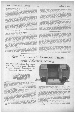
Again, with a view to maintaining concentricity, the flange holes are drilled after welding. In the machine, which forms both holes simultaneously, the job is located by gripping the tube, so that the holes are square and true in relation to the shaft. When shaft and joints are
assembled together, there remain the questions of balance and whip. Tests for the latter are made up to speeds .of 5,500 r.p.m., according to application, expert operatives conducting them. These men, by a high degree of specializing, can detect faults without the aid of scientific apparatus.
Balancing, however, is done in a manner which strikes the visitor as more precise. A Hofmann Kunz dynamic balancer is used, and shafts found to be out of balance are remedied by welding-on small metal strips at the points indicated by this ingenious machine.
The principle of the apparatus is briefly this. A bed, on which the tube is rotated, is carried at three points—two knife-edges, taking most of the weight, and a spring, situated at one end. Thus, if the spinning shaft is out of balance, the bed will vibrate and this is indicated by a gauge. Rotating with the shaft is a head, composed of two discs. Each of these is individually out of balance, but they can be rotated, relatively, to balance one another.
Determining the Error.
Provision is made for adjusting the position of these discs while the shaft is in motion. Accordingly, if the shaft causes vibration, the movable disc is rotated, relative to the other disc, until the head is sufficiently out of balance to compensate the error of the shaft. 'fhen vibration ceases, and the magnitude of the fault can be read from a scale on the 'disc. To locate the position of the fault, means are provided for moving along the knife-edge support in relation to the bed. The whole operation is quickly carried out, and every complete Layrub shaft is thus tested before leaving the works.
This brief account of the manufacturing processes and testing operations will give some idea of the care that is devoted to maintaining high standards of workmanship. To these and to the desirable characteristics of the Layrub system, which we have outlined, may be attributed the present-day popularity enjoyed by this transmission unit.