


A Robustly Constructed PASSENGER CHASSIS on Modern Lines
Page 74

Page 75
If you've noticed an error in this article please click here to report it so we can fix it.
TTIHE first impression given by the .1 new HB-type Brockway chassis is that it is solidly built in every detail to withstand the rigours of modern highspeed passenger-transport duty. A more detailed examination of the chassis confirms that impression. This machine is intended for duty as a 28-32-seater and sells for £850 with normal control, or £895 with forward control. It is marketed by A. E. Tapper, and Co., 100, Palmerston Road, Kilburn, London, N.W.6.
Heat-treated high-tensile steel is Used for the frame, which has a maximum depth of 8i ins, and is laterally braced by five cross-members: the fourth and fifth ones are placed at the points where B38 the rear-spring anchorages occur. The 'front cross-member supports‘the forward end of the engine-gearbox unit, also the radiator, which has a Germansilver casing; rubber blocks carry the radiator core. The front ends of the main frame_ members are curved downward to form the anchorages for the springs.
Divided top leaves are used for the semi-elliptic front springs ; they are 3 ft. 10 ins, long and 3 ins. wide. The rear springs are underslung and are 5 ft. long and 31 ins. wide. The front end of each spring works on a shackle
pin, but the rear end carries a hardened; steel plate bearing on the underside of a roller with a Hyatt bearing ; hard enecl-steel plates are fixed to the sides of the bracket, and there is a check bolt below the end of the spring. One-inch bolts• hold the rear springs to the Kirkstall axle, which embodies a David
Brown worm gear giving a ratio of 61 to I. Three higher ratios are available if desired. The worm is below the wheel and the axle pot is central.
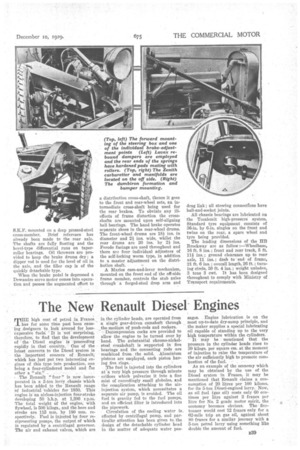
The six-cylindered engine is mounted at three points in the frame: the first consists of ae split bracket on the front cross-member; passing around the starting-handle boss on the crankcase; the other two are brackets on the frame, supporting the hearer arms, the connection being by means of spring-loaded bolts which give a degree of flexibility.
At 2,000 r.p.m. the output is 87 blip., or 70 b.h.p. at 1,400 r.p.m. The bore and stroke are 100 mm. and 130 mm.
respectively. The overhead valves are operated by push-rods, the valves being mounted in the detachable cylinder head. The cylinder block and the upper half of the crankcase are cast in one ; there are four 21-in, main bearings in the upper part of the case. In the sump is the oil pump, which delivers lubricant under pressure to all the principal bearings. An oil purifier is built into the system.
On the of side of the engine are the dynamo (C.A.V. 12-volt, 300-watt) and the Zenith pump-type carburetter. OL the near side are situated the oil filler, water pump and magneto with tandem
drive, the oil dip-stick and the geared starter. The lastnamed has a solenoid switch and an interrupter switch. The latter breaks the ignition circuit if the control be not fully retarded, thus avoiding --L a backfire with consequent damage to the starter.
Fuel is fed to the carburetter from the 36-gallon tank on the near-side eh aa els member by an Autovac tank, the petrol passing through a Zenith filter ; a two gallon reserve is provided.
A multi-plate clinch is used ; this has a ball-bearing spigot and withdrawal collar. Provision is made for lubricating the withdrawal from outside the casing. A Brown-Lipe four-forwardspeed gearbox is bolted to the engine, thus forming a unit. The indirect ratios are :-1st, 5.35 to 1; 2nd, 2.84 to 1; 3rd, 1.76 to 1; reverse, 6.30 to 1. Control is by a centrally placed lever, beside which is the hand-brake lever.
Three Hardy-Spicer universal joints are used in the divided propeller shaft ;• the centre bearing is a self-aligning S.K.F. mounted on a deep pressed-steel cross-member. Brief reference has already been made to the rear axle. The shafts are fully floating and the bevel-type differential runs on taperroller bearings. Oil throwers are provided to keep the brake drums dry ; a dipper rod is used for the level of oil in the axle, and the filler cap is of the quickly detachable type.
When the brake pedal is depressed a Dewandre servo motor comes into operation and passes the augmented effort to a distribution cross-shaft, thence it goes to the front and mar-wheel sets, an intermediate cross-shaft being used for the rear brakes. To obviate any illeffects of frame distortion the crossshafts are mounted upon self-aligning ball bearings. The hand brake operates separate shoes in the rear-wheel drums. The front-wheel drums are 181 ins, in diameter and 21 ins, wide, whilst the rear drums are 20 ins. by 21 ins. Ferodo facings are used throughout and there are four individual adjusters of the self-locking worm type, in addition to a master adjustment on the distribution shaft.
A Manes cam-and-lever mechanism, mounted on the front end of the off-side frame member, controls the stub axles through a forged-steel drop arm and drag link ; all steering connections have ball-and-socket joints.
All chassis bearings are lubricated on the Tecalemit high-pressure system. Standard tyre equipment consists of 36-in. by 6-in, singles on the front and twins on the rear, a spare wheel and tyre being provided.
The leading dimensions of the BB Brockway are as follow :—Wheelbase, 16 ft. 8 ins.; front and rear track, 5 ft.
111 ; ground clearance up to rear axle, 11 ins. ; dash to end of frame, 21 ft. 6 ins. ; overall length, 26 ft. ; turning circle, 59 ft. 4 ins.; weight unladen, 3 tons 3 cwt. It has been designed throughout to comply with Ministry of Transport requirements.