


Safety Device for Brake Failure
Page 66
If you've noticed an error in this article please click here to report it so we can fix it.
A Review of Recently Published Patents Specifications
ADEVICE for maintaining the working pressure in a hydraulic brake system should one of the pipelines develop a serious leak is described in patent No. 750,832 (C. Semenitz, Lohstrasse 3, Regenstauf, Germany).
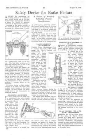
Attached to the master cylinder is the mechanism shown in the drawing. It consists of a balance-beam (1) carry ng a rubber-faced valve (2) on each end. The fluid inlet is shown at 3, whilst the outlets (4 and 5) lead to the front and rear brake systems, When the brakes are applied, the fluid, in passing the rubber-faced valves, tends to move them with it, but ai they are in balance no movement can occur during normal braking. If, however, an abnormal flow should occur from one of the outlets, the valve would be carried down and seated, thus cutting off the leaky line. The valve seating is also arranged to act as a switch for actuating a warning device on the dashboard.
In systems having a slight residual pressure at all times, the valve, once worked, would remain in the closed position. In other systems, the driver would have to act immediately on seeing the warning.
SOLDERING ALUMINIUM IT is well known that the oxide film I on aluminium is the only obstacle in the way of soldering it, and if it can be removed, ordinary soft solder will readily adhere. One of the latest methods is to break up the film by vibrating the soldering-iron at an ultrasonic frequency.
A scheme f 0r achieving the same end without the expense of providing an ultrasonic oscillator is shown in patent No, 750,401 (The Belark Tool and Stamping Co., Ltd., and O. Kriwaczek, 33 Sussex Place London, W.2.).
The tool consists of a normal type n32 of soldering-iron, preferably electrically heated, having buried in its nose a small stainless-steel wire brush (1). The shank of the brush is brought out to a simple buzzer device (2) operated by mains current.
The buzzer causes the wire brush vigorously to vibrate, which has the effect of scrubbing the surface of the metal. As the metal is cleaned under molten solder, the oxide film is unable to re-form owing to the absence of air.
ENGINE STARTING ARRANGEMENTS
FROM Texaco Development Corporation, New York, U.S.A. comes patent No. 750,954 dealing with improvements in a design of engine covered by an earlier patent (No. 596,846). This engine has special combustion arrangernents to permit the lower grades of fuel, such as paraffin and Diesel oil, to be used
successfully without knocking, even with compression ratios in the region of 10 to 1, The present patent deals with a means for facili tating starting when using these lowgrade fuels.
Dealing first with the main action of the engine, air is drawn in via a shrouded inlet valve which induces a vigorous swirl. Down stream injection follows during the period 70 to 20 degrees before top dead centre, and ignition is timed to occur when the leading edge of the fuel front reaches the sparking plug.
The present patent proposes, for cold starting, that the ignition should be delayed until the second time round of the mixture swirl, with or without enriching the mixture by closing the throttle (1). This may be performed automatically by coupling the ignition timer (2) to the injection-pump control
3), as indicated diagrammatically by the broken line (4) in the drawing.
COUPLING TRACTOR-TRAILER BRAKES WHILST a tractor-trailer cornhinaVV tion can be designed to have similar brakes, and the hydraulic systems can be coupled by a simple pipe, if a fleet
of vehicles has to be made interchangeable the correct braking ratio is not always obtained in practice.
A coupling device of use in such a circumstance is described in patent No. 750,646 by Alfred Teves, Maschinen und Arrna
turenfabrik K G . , Frankfurt-Main, ' Germany. The essence of the scheme is that the trailer mastercylinder is incorporated in the coupling and is worked by a direct mechanical thrust from the tractor system.
The drawing shows the coupling device in which the tractor braking pressure is applied
to the end (1). The trailer mastercylinder (2) is built on as a continuation of the body and the two systems are connected only by their respective pistons, the tractor piston (3) thrusting directly on to the trailer master-piston (4) when in operation.
The two units are separable by unscrewing a union nut (5) and each trailer can be provided with the piston diameter most suited to its brake characteristics, irrespective of the working pressure obtaining in the tractor. system.
GEAR CONTROL FOR AUTOMATIC TRANSMISSION PATENT No. 752,131 (Ford Motor
• Co., Ltd., 88 Regent Street, London, W.1) deals with a governor for controlling the functions of a semiautomatic transmission. The governor responds to engine speeds and works by pumping liquid through a venturi and using the pressure differential across it as the control factor.