


Uniform Facing-wear in 2LS Brakes
Page 58
If you've noticed an error in this article please click here to report it so we can fix it.
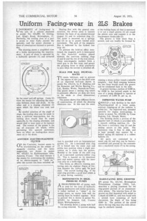
INIFORMITY of facing-wear is 16-) the aim of a schemes disclosed in patent No. 654,889, by Girling, Ltd., King's Road, Birmingham, 11. Normally, the trailing shoe of a pair is prone to wear badly nearest the spreader, and the patent discloses a form of construction claimed to prevent this.
The drawing shows a simplified view of a brake incorporating the improvement. A pair of shoes is operated by a hydraulic spreader (1) and retracted by the usual pull-off springs. Cams (2) form the means for adjusting the clearance between shoes and drum. At the other end is a sloping abutment (3) ,upon which the shoes can rock and slide.
• By careful selection of the angle of slope, the.leacting shoe can be made to have a uniform wear-pattern, but the trailing shoe would then be urged upwardly by the sloping abutment, and would tend to wear most at its topmost end. The essence of the patent is the use of stop-pins (4) which, whilst preventing this upward movement, have no effect on leading-shoe movement on to the drum.
ANOTHER ELECTRO-MAGNETIC CLUTCH
1-1N the Continent, interest seems to
he re-awakening on the subject of magnetic clutches, and the latest suggestions are shown in patent No. 655,025, by Etablissements Alba, Asnieres, France. The chief feature is the means for overcoming the tendency of an electro-magnet to "hold on" after the current has been switched off, Dealing first with the general construction, the driven plate is located between the faces of an annular-wound magnet (I) and its armature ring (2). The latter is mounted on a springy disc (3) so as to permit limited axial movement. The path of the magnetic flux is indicated by the broken line loop (4).
To prevent the hold-on effect mentioned, the magnetic path is interrupted by thin brass-foil washers placed between the cast-iron rubbing rings (5 and 6) and the rest of the iron circuit. These non-magnetic washers form a small gap in the flux loop, and permit the gripping force to drop practically to zero when the current is switched off.
SEALS FOR BALL JOURNALRACES TO retain lubricant, and to prevent the ingress of dirt are the chief aims of an improved bail-race shown in patent No. 654,314, by F. Hickling and the Ransorne and Manes Bearing Co., Ltd., Stanley Works, Newark-on-Trent. 'The patent shows a sealing ring which is extremely effective yet does not have to be made to close dimensional tolerances.
The patent shows four different forms of construction, of which the drawing illustrates one. In this case the outer race is provided with an hemispherical groove (1). An L-sectioned steel ring (2) is forced into the outer race and settles into position when a slight protrusion on it clicks into the groove. Bonded to the inside of the steel ring is an L-sectioned synthetic-rubber ring (3). This is tapered on its innermost part and makes contact with the inner race only on a knife-edge (4).
This forms an effective running seal, having only the slightest degree of friction between the rubber and •he hard steel. The curved leading edgx, af the . steel ring provides a good lead which is of value during assembly.
REFINEMENTS IN HIGHPRESSURE PUMPS A HIGH-PRESSURE oil pump, such PA as used for the rams of hydraulic tipping mechanism and similar purposes, is rather inclined to " sweat " at the casing joints, no matter how well the mating faces be bedded together. How to prevent this is shown in patent No. 655,031, by Integral, Ltd., Cousins Street, Wolverhampton.
The drawing shows a pump with half the casing removed. To prevent seeping at the bolting faces, all that is necessary is to cut a small groove (1) all round the pinion area and connect it to the low-pressure intake side (2).
The groove is little more than a scratch, and can readily be formed by running a sharp scriber round a suitable template. Any fluid creeping between the two faces would reach this groove and be conducted back to the inlet.
A groove having a section of 0.008 in. by 0.008 in. has proved ample in the case of a pump designed to operate at a pressure of 2,000 lb. per sq. in.
IMPROVED WATER PUMP QHOULD a leak develop in the shaft i..-)packing-gland of a water pump, constant topping-up of the radiator is called for. An improved seal, intended specially for engine water-pumps, is shown in patent No. 654,948, by Crane Packing, Ltd., Slough, Bucks.
The drawing shows a portion of the impeller hub (1) which is provided with a smooth rubbing end-face (2). On this bears a stationary ring (3) and the sealing occurs at this point. The stationary ring is free to slide, and is kept pressed into contact by a helical spring (4) enclosed in a rubber bellows (5).
All parts are contained in a metal cup (6) and they can be factoryassembled and pressed by the customer into a machined recess (7) in the casing.
HARD-FACING RING GROOVES I N patent No. 651,765, Birmingham Aluminium Castings (1903), Ltd., describes a plating treatment for the ring-groove portion of an aluminiumalloy piston. The wearing faces of the groove are first deposited with nickel to a depth of 0.008 in., and then faced with a second layer consisting of hard chromium, the depth of this being 0.003 in. The portion of the piston above the top ring may also with advantage be similarly treated.