


The Automatic Adjustment of Ignition Pumps
Page 54
If you've noticed an error in this article please click here to report it so we can fix it.
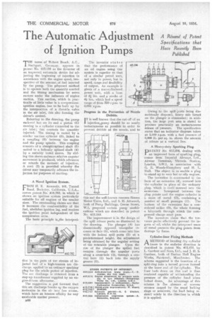
THE name of Robert Bosch, A.G., Stuttgart, Germany, appears in patent No. 412,136 as the inventor of an improved automatic device for adjusting the beginning of injection in accordance with the engine speed, irrespective of the amount of fuel injected by the pump. The p?oposed method is to operate both the quantity control and the timing mechanism by servo motors under the influence of engine suction. This suction, which is practically of little value in a compression. ignition engine, has to be built up by the interposition of a throttle valve in the air inlet, this also forming the driver's control.
Referring to the drawing, the pump rack-rod has on its end a piston (1) moving in a cylinder connected to the air inlet ; this controls the quantity injected. The timing is varied by a similar suction cylinder (3), linked to a coupling (6) between the engine and the pump spindle. This coupling consists of a straight-splined shaft (5) united to a helically splined shaft (4) by a suitably bored sleeve. By sliding this sleeve endways relative angular movement is produced, which advances or retards the moment of injection. A cord (2) is provided whereby the driver may temporarily advance the injection for purposes of starting.
A Novel Ignition System.
L.-ROM H. E. Kennedy, 105, Tunnel
Road, Berkeley, California, U.SA., comes patent No. 410,752, in which is shown an ignition system particularly suitable for oil engines of the smaller sizes. The outstanding claims are that it increases the combustibility of the fuel, abolishes ignition lag, and renders the ignition point independent of the compression ratio.
The basic principle is,‘the interposi
tion in the .parn of the stream of injected fuel of a high-tension arc discharge, applied by an ordinary sparking plug for the whole period of injection. The arc discharge is obtained from a step-up transformer supplied by an engine-driven alternator.
The suggestion is put forward that this arc discharge breaks up the oxygen molecules in the air into free atoms, which have an intense affinity for any oxidizable matter present.
B44 The inventor states that the performance of an oil engine using this system is superior to that of a similar petrol unit, not only in power, but in speed, range and flexibility of output. An example is given of a four-cylindered power unit, with a bore of 31 ins, and a stroke of ins., which had a speed range of from 250 r.p.m. to 4,000 r.p.m.
Progress in the Prevention Dribble.
IT is well known that the cut-off of an 1 inject oni?pump should be as nearly instantaneous as possible in order to prevent dribble at the nozzle, and to
this end the well-known concern Simms Motor Units, Ltd., and S. H. Attwood, both of Percy Buildings, Gresse Street, W.1, proposed certain pump modifications which are described in patent No. 412,243.
The improvement is in the design of the spill release ports, as illustrated in the drawing. The plunger (4) has diametrically opposed triangular recesses or flats (5), which come into line with the helical spill ports (1) at a predetermined height, the adjustment being obtained by the angular setting of the rotatable plunger. Upon the rise of the plunger the spilled fuel escapes through the angular ports along a cross-hole (3), through a central bore (2) back into the supply groove (6). Owing to the spill ports being diametrically disposed, heavy side thrust on the plunger is eliminated; in addition, the large port area is stated to produce practically an instantaneous release of pressure. The specification states that an indicator diagram taken at 1,000 r.p.m. with a fuel pressure of 6.000 lb. per sq. in. shows the amount of release as a vertical line.
A Heavy-duty Sparking Plug.
PATENT No. 412,294, dealing with an improved form of sparking plug, comes from Imperial Airways, Ltd., Airway Terminus, Victoria Station, London, S.W.1, in association with G. E. Woods-Humphery and H. L. Hall. The object is to enable a plug to stand up to very hot or oily engines.
The invention is constructed in the form of an extension (4), screwed into the cylinder in place of the ordinary plug, which is itself screwed into the extension. Interposed between the plug points and the engine cylinder is a mass of metal (3), containing a number of small passages (1). The bottom of the extension has a constricted orifice (2), the whole forming a labyrinth through which the compressed charge must pass.
The inventors claim that the tortuous paths effectively prevent the ingress of oil, whilst the interposed mass of metal protects the plug points from damage by flame.
Cylinder-liner Fixing Methods
AMETHOD of locating dry cylinder liners in the endwise direction is described in patent No. 412,153, by L. Gardner and Sons, Ltd., and J. H. S. Gardner, both of Barton Hall Engine Works, Patricroft, Manchester. The scheme suggested is the insertion of a split-ring into a turned groove formed at the lower end of the cylinder. The liner beds down on this and is thus rendered capable of withstanding the pressure of the cylinder head when bolted down. An advantage of this scheme is the absence of uneven stresses caused by the usual locking rings or setscrews, the load being resisted solely in the direction in which it is applied.