


An Eight-speed Gearbox A GEARBOX giving eight forward ..t - k speeds
Page 56
If you've noticed an error in this article please click here to report it so we can fix it.
yet needing only five pairs of gears is disclosed in Patent No. 686,782, by A. Taylor and David Brown and Sons (Huddersfield), Ltd., Park Works, Lockwood, Huddersfield. Two reverse speeds are also available through an additional two pairs of gears.
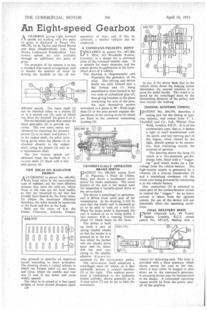
The principle of the scheme is to use a standard four-speed arrangement, and to double the number of ratios by driving the layshaft at one of two different speeds. The input shaft (1) can be clutched either to a pinion (2) or to a second one (3), each of which can drive the layshaft via gears 4 or 5.
The two layshaft speeds thus enable the three gear-pairs (6) to provide six ratios. The two other ratios are obtained by clutching the primary pinion (2) to its shaft, and pinion 3 to the output shaft; the other ratio being given when the p1nion (2) is clutched directly to the output shaft, using the pinion (3) only as a transmission shaft.
The two reverse speeds are obtained from the layshaft by a reverse shaft (7) fitted with a slid' able pinion (8).
NEW IDEAS ON RADIATOR DESIGN •
A CCORDING to patent No. 686,902, /-1 the front tubes in the conventional type of radiator, are the most effective because they meet the cold air, whilst those at the rear are the least useful, as they are traversed by air that has already been heated by the front tubes. To obtain the maximum efficiency therefore, the tubes should be numerous at the front and few at the back.
Such are the views of S.A. des Usines Chausson, Asnieres, France,
who proceed to describe an improved layout according to these principles. The drawing shows a typical scheme in which the frontal tubes (1) are many and close, whilst the middle and rear sets (2 and 3) are fewer and more widely spaced.
The ideal to be aimed at is that equal weights of metal should dissipate equal A38 quantities of heat, and if this be achieved, a smaller radiator can be employed. • A CONSTANT-VELOCITY JOINT
DISCLOSED in patent No. 687,286, T. Hirst, 163 Woodside Avenue, Coventry, is a design for a universal joint of the constant-velocity type. It is suitable for many purposes, and the patent shows its application to the frontwheel drive of a vehicle.
The drawing is diagrammatic and illustrates the geometry of the joint. The driving and driven shafts are each formed into a flat forked end (1) being assembled in slots formed in the two ends of cylindrical pins (2), thus giving freedom in the plane containing the axis of the pins; the pins themselves permit movement in a plane at 900. Wide-angle Slots (3) in the pins permit angular displacement of the uniting rivets (4) which are fixed to • the common connecting housing (5).
CENTRIFUGALLY OPERATED BRAKE SERVO DATENT No. 686,969, comes from 1 G. Piganeau, 3 Place de rAlma. Paris, and shows a mechanical servo motor for brake assistance. The novel feature of the unit is the means used for imparting a variable-speed drive to the servo-motor.
The device is centrifugal in operation, and is driven from some part of the transmission. In the drawing, it will be seen that the whole unit is mounted so as to be able to rock on a bolt (I). When the brake pedal is depressed, the unit is rocked so as to bring pulley 2 into contact with a running frictionwheel (3) which bears on the faces.
The pulley is built up from a pair of 684,791 rpring loaded cheeks so that the harder it is pressed on to the friction wheel the farther will the cheeks move apart and the faster will the unit run, owing to the smaller effective diameter assumed by the servo-motor pulley.
The servo-motor itself comprises a centrifugal mass (4) which, as it flies outwards, presses a conical member (5) to the right. This endwise movement is transmitted to the hydraulic master cylinder, shown generally at 6. A stop screw (7) can be set to limit the movement. In use, if the driver finds that as the vehicle slows down the braking action diminishes, his natural reaction is to press the pedal harder. The result is to speed up the centrifugal mass by the diminishing diameter of the pulley, and thus restore the braking.
TESTING IGNITION TIMING
1DATENT No. 684,791, describes a 1 testing tool for the timing of ignition systems, and comes from V. L. Churchill and Co., Ltd., Walnut Tree Walk, London, S.E.11. It is of the stroboscopic type, that is, it flashes a light in exact synchronism with the spark, and any moving part of the engine, when viewed by the light, should appear to be stationary, thus indicating exactly the moment of ignition.
The drawing shows the lamp (I) which is a two-electrode gas-discharge tube, fitted with a " triggering" grid which works on a low voltage from the vehicle battery. The high-tension supply is generated by a vibrator (2) a itep-up transformer (3) and a smoothing condenser (4), the whole unit being powered by connecting it to the vehicle battery.
One connection (5) is attached to some part of the contact-breaker circuit to control the "trigger." As no heavy current is taken from the ignition system, the use of the device will not materially affect the operating conditions.
COAL DELIVERY BODY
FROM Charrold Ltd., 40 Trinity Square, London, E.C.3, comes patent No. 687,435, dealing with a
vehicle for delivering coal. The body is provided with a floor conveyor which slowly moves the coal to the rear, where it may either be bagged or shot direct on to the customer's premises. A screening device may be incorporated in the design. A convenient operating means would be from the power takeoff of the gearbox.