


Perkins Launch a Dollar Earner
Page 42
Page 43
If you've noticed an error in this article please click here to report it so we can fix it.
BUlLT as a compact unit of high output per-litre capacity, the Perkins R-type six-cylindered oil engine is designed primarily for installing in American 5-ton chassis, where it will provide a cruising speed of 55-60 m.p.h., and for use in British 7-tonners. It is also anticipated that it will be employed in British export 5-tonners, articulated tractors and for amidshipmounting in a passenger chassis. Chassis manufacturers are expected to make early announcement of this unit being available in their respective models.
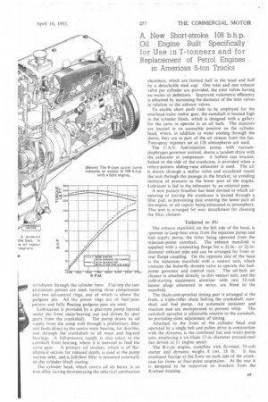
The new engine, of 340 cu. in. (5.56 litres) capacity, develops 108 b.h.p. at 2,700 r.p.m., its maximum governed speed. Complete with exhauster, fan and dynamo, the output is 101 b.h.p. at 2,700 r.p.m. To — ensure reliability for prolonged high-speed operation the stroke dimension has been restricted to 4+ in., affording a piston speed of slightly over 2,000 ft. per minute at 2,700 r.p.m. Bore diameter is 4 in. The torque curve is almost flat from 1.500-1,750 r.p.m., at which period 240 lb.-ft. gross torque is derived. This power output compares favourably with that of the American petrol engines which the R-type engine is intended to replace.
Other features of this new unit include aluminium die castings for the cylinder-head cover and sump, the last being a reversible component with a removable well. The Aeroflow system of combustion is retained and cold-starting equipment is fitted. A new-type crankcase breather is ineorriorated and provision is made for a compressor or exhauster to be fitted according to the braking system.
Compact Dimensions
The short stroke has enabled the unit to be built shallf,w. so adding to its interchangeability with a petrol engine in a normal-control chassis without extensive modification to the bonnet or mounting points; the sump is shaped to afford maximum groundand axleclearance. Complete with an oil-bath air cleaner mounted on the intake manifold, the engine is 3 ft. 31 in. deep, 1 ft. 11+ in. wide and 3 :ft. 21 in. from the starter dog to the crankshaft flywheel flange. Clutches of'up to I8-in. diameter can be accommodated.
The crankcase-cylinder-block casting, made of cast iron, is designed for the fuel-injection pump and brake exhauster or compressor to be mounted on the left-hand side, and has an extended skirt below the crankshaft centre line, with ribs and transverse webs at each main bearing for additional rigidity.
A seven-bearing induction-hardened crankshaft is employed, with a viscous-fluid damper at the front to eliminate all severe torsional vibration. End thrust is taken by a steel-backed bronze-faced washer located at the rear main journal. In common with modern practice pre-finished thin-shell bearings are employed for the main and big-end bearings, the shells being lined with indium-flashed lead-bronze and located in position by tabs fitting into the crankcase, bearing caps and connecting rods.
The connecting-rod bearing is split horizontally and the cap located by serration's which mate with the rod, There is sufficient room for the connecting rod to be sit withdrawn through the cylinder bore. Flat-top die-east aluminium pistons are used, having three compression and two oil-control rings, one of which is above the gudgeon pin. All the piston rings are of butt-joint pattern and fully floating gudgeon pins are used.
Lubrication is provided by a gear-type pump located under the front main-bearing cap and driven by spur gears from the crankshaft. The pump draws its oil supply from the sump well through a preliminary filter and feeds direct to the centre main bearing, for distribution through the crankshaft to all main and big-end bearings. A full-pressure supply is also taken to the camshaft front bearing, where it is metered to feed the
valve gear. A primary oil strainer, which is of flatelliptical section for reduced depth, is used at the pump suction inlet, and a full-flow filter is mounted externally on the cylinder block casting.
The cylinder head, which covers all six bores, is an iron-alloy casting incorporating the spherical combustion chambers, which are formed half in the head and half by a detachable steel cap. One inlet and one exhaust valve per cylinder are provided, the inlet valves having no masks or deflectors. Improved volumetric efficiency is obtained by increasing the diameter of the inlet valves in relation to the exhaust valves.
To enable short push rods to be employed for the overhead-valve rocker gear, the camshaft is located high in the cylinder block, which is designed with a gallery for the cams to operate in an oil bath. The injectors are located in an accessible position on the cylinder head, where, in addition to water cooling through the sleeve, they are in part of the air stream from the fan. Two-spray injectors set at 120 atmospheres are used.
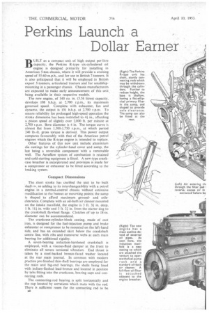
The C.A.V. fuel-injection pump, with vacuumdiaphragm governor control, shares a tandem drive with the exhauster or compressor. A hollow cast bracket, bolted to the side of the crankcase, is provided when a rotary-pattern sliding-vane exhauster is used. The air is drawn through a snifter valve and circulated round the unit through the passage in the bracket, so avoiding increase of pressure in the lower part of the engine. Lubricant is fed to the exhauster by an external pipe.
A new pattern breather has been devised in which air entering or leaving the crankcase is passed through a filter pad, so preventing dust entering the lower part of the engine, or oil vapour being exhausted to atmosphere. This unit is arranged for easy detachment for cleaning the filter element.
Tailored to Fit The exhaust manifold, on the left side of the head, is upswept to keep heat away from the injection pump and fuel supply pump, the latter being operated from the injection-pump camshaft. The exhaust manifold is supplied with a connecting flange for a 21-in.or 2i-indiameter exhaust pipe and can be arranged for front or rear flange coupling. On the opposite side of the head is the induction manifold with a venturi unit, which contains the butterfly throttle valve to operate the fuel pump governor and control rack. The oil-bath air cleaner is attached directly to this venturi unit, and the cold-starting equipment atomizer with two 12-volt heater plugs connected in series, are fitted to the manifold.
The chain-and-sprocket timing gear is arranged at the front, a triple-roller chain linking the crankshaft, camshaft and fuel pump. An automatic tensioner and reaction pad are incorporated to prevent whip. The camshaft sprocket is adjustable relative to the camshaft, so providing close adjustment of timing.
Attached to the front of the .cylinder head and operated by a single belt and pulley drive in conjunction with the dynamo, is the combined fan and water-pump unit, employing a six-blade 17-in.-diameter pressed-steel fan driven at 11 engine speed.
The R-type engine, complete with flywheel, 24-volt starter and dynamo weighs 8 cwt. 18 lb. It has machined facings at the front on each side of the crankcase for threeor four-point suspension. At the rear it is designed to be supported on brackets from the flywheel housing.