


A FREE-WHEEL DEVELOPMENT.
Page 68
If you've noticed an error in this article please click here to report it so we can fix it.
A Résumé of Recently Published Patent Specifications.
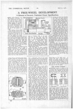
THE names Ifumfrey and Sandberg, of London, already well known in connection with the recent application of the free wheel to automobiles, appear, in specification No. 286,889, in which certain recent developments are described connection the reversingMOvement and the use of the engine as a brake. . The attitude of the public towards the free wheel, so far as we can judge, is one of unwillingness to sacrifice the advantage of being able to emPloy the engine as a brake. In all probability this feeling will die down owing to recent improvements that have been made in brakes,such as the introduction of front-wheel brakes and power-assisted brakes, but, while the feeling of uncertainty exists, the public will probably demand a free-wheel device in Which the engine Can be engaged whilst running down a.hill, even if the engine should have 'stopped. One Of the features claimed for the Humfrey-Sandberg device is that a gradual engagement of the engine is possible, and the present patent deals Particularly with this phrt of the mechanism. The main features of the device and the means of procuring a unidirectional drive by means of skewed rollers has been fully described in our issue of October 11th, so we propose here to deal only with that part of the mechanism that relates to converting the unidirectional drive into a bidirectional drive. Attached to that part of the shaft which extends at the rear of the gearbox is thebell-shaped member shown; this has internal splch engage with the two conical members which lie otItsideskewed rollers. The left hand of these members actuates the forward drive through the jamming of the skewed rollers on the inner conical member. The two conical members on the right are those with which we are particularly concerned, as, so long as these members are .in the position shown, with the row of balls forcing the inner one towards the right, the space between the two cones is duch that no jamming of the skewed rollers can take place, consequently the free. wheel is in action. It will be seen that the row of balls is held in the position shown by means of the gliding member, which, while in its present position, prevents the, balls from escaping from between the collar and the end of the sleeVe of the reverse Clutch: If the sliding Collar be moved gradually towards the left, it will permit the balls to' escape gradually and will allow the spring which separates the two clutches to assert itself, to push' the reverse clutch towards the' left, and gradually to grip the skewed rollers, thus altering the unidirectienal drive into a bidirectional drive and allowing
be engaged. • ••
-We notice that dog engagement is shown on the flange of the sliding collar so thught into positive engagement With the bell-shaped member, so forming a positive drive. We also notice that positive ratchet-shaped teeth are mentioned as a means of obtaining the bidirectional drive. We are somewhat surprised at this, as we had considered that the gradual takeup of the engine was one of the imtiu features of the device, A New Form of Universal Joint.
THE all-metal universal joint is still one of the most imperfect parts of the modern automobile, for, as is well known, if the rotation of the driving shaft is uniform this is not the case with the driv--, shaft, when the two shafts are not in axial alignment, as the driven shaft will pass through two periods of high speed and two periods of'low speed at each complete revolution. ' It is true that if two universal joints are employed, one at each' end of the propeller shaft, they can be so set that a high-speed period of one joint can synchronize with a low-speed period of the joint at the other end of the pro" yeller shaft, but this can only be possible when the two shafts to which the propellershaft' is coupled are in a parallel line with each other, which' is
not always possible.
In the Hooke joint, or any variation of the same principle, the axis of each separate joint always lies at a right angle with the shaft to which it is rigidly connected, but in the device shown in patent No. 274,857, Edmond Parville, of Paris, it is claimed that each of the axes of the joint can take up a position which is mid-way between the two shafts; in other words, the angle formed by the two shafts is always bisected by the axis of the joint. The construction of the joint is as follow :—A cylindrical member (A) has a hole through its centre at right angles to its own axis, and is turned on the outside to form a' series of ridges and grooves. A larger cylindrical member (B) is bored with ridges and grooves 'which will mesh with those on (A). The 'outside of (B) is also turned so as to form ridges and groove; and after this (B) is cut into two portions, leaving space, as shown in the lower view, so that the shafts can assume an angle as shown in dotted lines. Outside (B) there are the two members, which may be formed integral with the shafts, or may be separate fittings. The inner faces of these memhers are bored to mesh with the outside of (B), and then cut away to make clearance for the angle of the two shafts, as shown in
dotted lines in the upper view. A
central bolt with a large head and Hanged nut passed through the centre of(A), and its head and flange are said
• to act on the cam-like surfaces of the outer members and thus to 'control the axis of (A) so that it always bisects the angle of the two shafts.
Still Another Locknut. ANOTHERlocknnt is added to the already long list of such devices by the patent, No. 286,120; of, Lee Olaf Planer and Frans Neff, both of Munich. The nut consists of a stamping from sheet metal, which is bent into the form of the letter LI, having two holes tapped to fit ,the bolt for which it is to secure an ordinary nut from cocominglOose. The two tapped in axial alignment, twist is -given to the connecting part after tapping. When screwed in place, a pressure is set up on the bolt which prevents the locknut from coming loose, as the two holes are then brought into axial alignment.