


A DOUBLE CROWN-BEVEL DRIVE.
Page 30
If you've noticed an error in this article please click here to report it so we can fix it.
A Résumé of Recently Published Patents
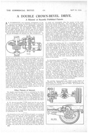
AN INTERESTING and ingenious arrangement of the final-drive mechanism of a bevel-driven axle is described specification No.-193,504, by F. Barbagallo. Instead of only one crown bevel and corresponding pinion being used for this transmission, two arc employed. They are placed • back to back : each has its own pinion, and the two pinions are mounted on parallel shafts, one of 'which is 'driven direct by the propeller shaft and the other from it by spur gears. . Several advantages are elaimed for Ws arrangement. In
the first place the usual thrust, which is brought about when power is transmitted between a pair of bevel wheels, is, in this ease, neutralized, as one reacts against the ,other.. Incidental to this ie the absence of a tendency for the gears to push one another out of mesh, and a decreased tendency to mal engagement from the same cause. Wear of the teeth is diminished, and the need for a ball thrust bearing is p'ractically eliminated. The number of teeth in. mesh, transmitting the power, is double that of the ordinary construction, employing only one pair of bevels, so that smaller gears can safely be used.
Most of the interest lies in the arrangement of the two crown bevels, which are disposed back to back. One of them is bolted to the differential gear. The other is mounted on the 'boss of the first named, and is secured to it by screws, which are arranged so that a certain amount of relative movement, as between one wheel and the other, is possible, the actual movement being limited in extent by the length of the slot into which the screws engage. Projections, or lags, on the back of on wheel fit into elongated grooves in the other, and on each side of the lugs are springs, which butt, at their other ends, against the ends Of the grooves. The combination of springs and lugs, bolts and slots allowS the two bevels to adjust themselves sliglatly to the relative positions of the teeth on the driving bevel pinions.
Other Patents of Interest.
The double-reduction gear' which is patented by the International Motor Co., of U.S.A., is of a type familiar to most commercial vehicle users in this country. The principal claim appears to be•for the inclination which the double-banjo makes to the horizontal. This is quoted in the specification, Yo. 193,7103, as being 45 degrees, and it is stated that the strain on the axle is best resisted by the form and relation. described.
E. W. Seward provides a solid band tyre for use on the wheel of an agricultural tractor, mounted on a metal base, which is in two parts. The halves are drawn together on the rim by bolts, which pass through angle-iron flanges mounted on the ends of the metal bases for the tyre, and the tyre is farther secured by a number of hook bolts which pass through the rim of the wheel itself. The invention is described in specification No. 193,730.
An alternative to the usual ratchet and pawl, as a means of holding a hand braka in the operative position, is described in specification No. 193,753, by H. Marchand. The illustration Which accompanies the speCification shows a cableoperated brake, but the other type may be employed if desired. . The, brake fever is. in two parts—an outer tubular, one and an inner, which, in the 'case of a eable brake, is also tubular, The outer part is attached to a knob or handle at its upper end, and at its lower end. carries a worm,. the teeth B44
of, which are interrupted, after 'the manner of the screw thread of a bayonet-type joint.. The worm may, by the halfturn of the handle of 'the brake lever, be engaged or disen• -gaged with a series of teeth which are mounted on the brake brecket which is bolted to the chassis frame: Normally, the worm teeth are not in 'engagement with those on the bracket; and, for an Ordinary application of the brake, for temporary cause, as in traffic; they-remain disengaged. When a stop of considerable duration is desired, the brake is applied, and the handle given a half-turn, engaging the worm teeth with those of the bracket, and retaining the brake' in the " on " position. It should be observed that this arrangement extends the scope of the hand brake by making it more convenient to use as an entergency brake,' Since the teeth d5 not invariably engage, as' in the ordinary case where a ratchet. is employed.
An improved steering gear for a six-wheeled vehicle, of the tractor-trailer type, haviitg: four-wheeledr traPtor and a twb-wheeled trailer, the connection between the two being a single pivot, at the rear-of the ti-actor, is described in specification No. 193,800, by G. Page and L. Dewing. A bevel wheel is mounted on the steering pivot of the off-side front wheel of the tractor, and on the pivot of the near-side wheel of the trailer. A diagonally arranged shaft transmits the movement of the former to the latter, so that the wheels of the trailer, which are attached to an axle of the Ackerman type, move through the same steering angle as the front wheels of the tractor.
An interesting improvement in the construction of a motor poach hood is described in specification No. 193,644, by E. H. Dew. Tho object is to Support the weight of the hood and its sticks during' the time it is being moved forward or backward in the process of being raised or lowered. The applis anoe, for such it really is, may be fitted to existing vehicles and hoods. It consists of a U-shaped member; having each leg of the U secured to one part Of the body of the vehicle in such a manner that the ridge of the U. is longitudinally disposed. Additional supports for the ridge may also be provided, in the shape of legs, which are also mounted on the bodywork. The attachments are such that when the hood has been lowered the U-shaped piece may also be lowered to one side.of the coach, so that it is entirely hinen, and does not interfere with the comfort of the passengers.
The peculiar change-speed gear which is the subject of specification No, 193,645, by C. 13aradat, embodies the combined actions of a ratchet and free wheel. It is stated to be progressive and.automatic.