 1
1 2
2 3
3 4
4 5
5 6
6 7
7 8
8 9
9 10
10 11
11 12
12 13
13 14
14 15
15 16
16 17
17 18
18 19
19 20
20 21
21 22
22 23
23 24
24 25
25 26
26 27
27 28
28 29
29 30
30 31
31 32
32 33
33 34
34 35
35 36
36 37
37 38
38 39
39 40
40 41
41 42
42 43
43 44
44 45
45 46
46 47
47 48
48 49
49 50
50 51
51 52
52 53
53 54
54 55
55 56
56 57
57 58
58 59
59 60
60 61
61 62
62 63
63 64
64 65
65 66
66 67
67 68
68 69
69 70
70 71
71 72
72 73
73 74
74 75
75 76
76 77
77 78
78 79
79 80
80 81
81 82
82 83
83 84
84 85
85 86
86 87
87 88
88 89
89 90
90 91
91 92
92 93
93 94
94 95
95 96
96 97
97 98
98 99
99 100
100 101
101 102
102 103
103 104
104 105
105 106
106 107
107 108
108 109
109 110
110 111
111 112
112 113
113 114
114 115
115 116
116 117
117 118
118 119
119 120
120 121
121 122
122 123
123 124
124 125
125 126
126 127
127 128
128 129
129 130
130 131
131 132
132 133
133 134
134 135
135 136
136 137
137 138
138 139
139 140
140 141
141 142
142 143
143 144
144 145
145 146
146 147
147 148
148 149
149 150
150 151
151 152
152 153
153 154
154 155
155 156
156 157
157 158
158 159
159 160
160 161
161 162
162 163
163 164
164 Universal -joint Modifications
Page 128
If you've noticed an error in this article please click here to report it so we can fix it.
A'UNIVERSAL joint which not only permits angular displacement, but also allows of axial extension, is shown by C. A. G. Standage, 66, Redcliffe Gardens, London, SAVA°. in patent No. 403,382. The invention consists of what amounts to a spherical gearwheel enveloped by an internal gear. The internal gear is unusual, however, in so far as its teeth consist of bunches of small spring blades suitably held in the outer casing. The drawing illustrates one form of construction, the form of the gear teeth (1) in this case being doubly convex.
It is claimed that this coupling gives a constant velotity ratio, and owing to being axially movable, avoids the need for an extensible cardan shaft.
A Carburetter with a Venturi of Variable Diameter.
DATENT No. 402,592, by E. S.
Almaraz and another, 16, Salvador Crespo, ChaMartin de la Rosa, Madrid, Spain, describes a carburetter with a venturi tube of variable diameter. In the usual type of carburetter, the velocity of the air through the venturi varies at the throttle opening, which tends to weaken the mixture at low engine speeds; this necessitates the use of auxiliary jets and similar compromises. A venturi of variable diameter should overcome this defect, and ,according to the specification this in
vention will provide a mixture of Constant proportions at all engine speeds.
The illustration shows three positions of a carburetter embodying the invention. The venturi is made of a large number of thin blades, fixed at top and bottom to rings, by pressing these rings together the blades are made to spring towards the centre, thus restricting the bore, In operation the top ring is worked by a cam on the throttle spindle ; the lower ring is stationary, but adjustable to suit variations in fuel, atmospheric conditions, or altitude in the case of aircraft.
A Cylinder-liner Novelty.
pATENT No. 403,479, by J. W. Bailey, 151, Ducklen Hill Lane, London, N.W.10, shows an unusual method of holding cylinder liners in
D14
position. Between the cylinder head and the cylinder block is clamped a metal plate having holes cut therein for each cylinder. The liners are screwed and locked into these holes, the lower ends being coned to suit corresponding seatings at the bottom of the cylinder block.
These seatings must, of course, be water-tight, and it would appear that the success of the scheme depends entirely upon the .facility with which this is achieved; especially as the explosion pressure would tend to lift the liners from their seats. The inventor claims that the scheme will save a great deal of time and labour compared with previous methods, owing to the ease with which a new liner could be fitted.
Automatic Adjustment of Brakes.
BRAKE-MECHANISM improvements are dealt with in patent No. 401,273 from W. Saward, 238, Kensington
Street, Girrington, Yorks. The object of this invention is to enable slackness in the brake rods to be taken up automatically.
The means suggested to achieve this end is to include a ratchet and pawl mechanism on the brake-gear crossshaft to which the pedal rod is connected. In operation, when the pedal is released, if it should come back more than the brake gear, it can gain a tooth in the ratchet, and thus obtain a fresh hero position. This invention appears to be open to the objection . that should the brake shoes stick for a moment when the pedal is released, several teeth would be gained by the ratchet, thus giving a zeto position With brakes on!
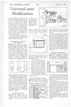
Detachable-rim Construction.
AN improved design of detachable rim is disclosed in patent No. 403,468, by V. Caro, 229, London Road, Reading. In this invention the Tim consists of a main portion (1) and a detachable ring (2). The ring is held on to a conical seating by clamps and bolts, pressing on a split-ring (3). This split-ring is located in an annular groove (4). at the base of the cone On the main body,
The inventor claims that the operation of slackening the set of clamp nuts is itself sufficient to break the seal of paint and rust which inevitably forms on all devices of this type. The force required to break this joint is provided by the side pressure from the tyre walls, but we should imagine that this would be diminished, if not absent, in the case of a flat tyre.
The specification shows in addition a method of applying the invention to a twin-tyre rim, in which a central spacing collar has two rim edges formed upon it.