 1
1 2
2 3
3 4
4 5
5 6
6 7
7 8
8 9
9 10
10 11
11 12
12 13
13 14
14 15
15 16
16 17
17 18
18 19
19 20
20 21
21 22
22 23
23 24
24 25
25 26
26 27
27 28
28 29
29 30
30 31
31 32
32 33
33 34
34 35
35 36
36 37
37 38
38 39
39 40
40 41
41 42
42 43
43 44
44 45
45 46
46 47
47 48
48 49
49 50
50 51
51 52
52 53
53 54
54 55
55 56
56 57
57 58
58 59
59 60
60 61
61 62
62 63
63 64
64 65
65 66
66 67
67 68
68 69
69 70
70 71
71 72
72 73
73 74
74 75
75 76
76 77
77 78
78 79
79 80
80 81
81 82
82 83
83 84
84 85
85 86
86 87
87 88
88 89
89 90
90 91
91 92
92 93
93 94
94 95
95 96
96 97
97 98
98 99
99 100
100 101
101 102
102 103
103 104
104 105
105 106
106 107
107 108
108 109
109 110
110 111
111 112
112 113
113 114
114 115
115 116
116 117
117 118
118 119
119 120
120 121
121 122
122 123
123 124
124 125
125 126
126 127
127 128
128 129
129 130
130 131
131 132
132 133
133 134
134 135
135 136
136 137
137 138
138 139
139 140
140 141
141 142
142 143
143 144
144 145
145 146
146 147
147 148
148 149
149 150
150 151
151 152
152 153
153 154
154 155
155 156
156 157
157 158
158 159
159 160
160 161
161 162
162 163
163 164
164 165
165 166
166 167
167 168
168 169
169 170
170 171
171 172
172 173
173 174
174 175
175 176
176 177
177 178
178 179
179 180
180 CENTRING HARDY FLEXIBLE COUPLINGS.
Page 124
If you've noticed an error in this article please click here to report it so we can fix it.
A Résumé of Recently Published Patent Specifications.
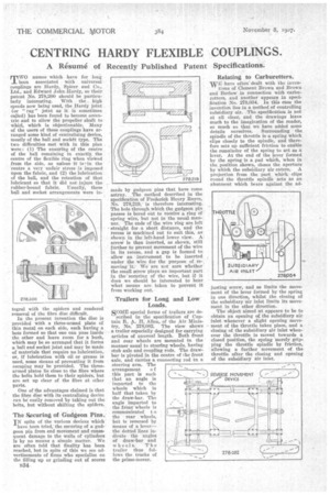
M WO names which have for long
been associated with universal couplings are Hardy, Spicer and Co., Ltd., and Edward John Hardy, so their patent No. 278,200 should be particularly interesting. With the high speeds now being used, the Hardy joint . (or " rag" joint as it is sometimes culled) has been found to become eccentric and to allow the propeller shaft to whirl, which is objectionable. Many of the users of these couplings have arranged some kind of centralizing device, mostly of the ball and sock6t type. The two difficulties met with in this plan were: (1) The ensuring of the centre of the ball remaining in exactly the centre of the flexible ring when vieived from the side, as unless it is...in the centre a very unfair stress is imposed upon the fabric, and (2) the lubrication of the ball, and the retention of that• lubricant so that it did net injure the rubber-bound fabric. Usually-, these ball and socket arrangements were in
tegral with the spiders and rendered removal of the fibre disc difficult.
In the present invention the disc is provided with a three-armed plate of thin metal on each side, each having a boss formed so that one can pass inside the other and leave room for a bush, which may be so arranged that it forms a ball and socket joint and may be made of materials that require no lubrication, or, if lubrication with oil or grease is used, some /anus of preventing it from escaping may be provided. The threearmed plates lie close to the fibre where the bolts hold them to their spiders, but are set up clear of the fibre at other parts.
One of the advantages claimed is that the fibre disc with its centralizing device can be easily removed by taking out the bolts, but without shifting the spiders.
The Securing of Gudgeon Pins.
IN spite of the various devices which have been tried; the securing of a gudgeon pin from end movement and consequent damage to the walls of cylinders is by 110 means a simple matter. We are often told that finality has been reached, but in spite of this we see advertisements of firms who specialize on the filling up or grinding out of scores made by gudgeon pins that have come astray. The method described in the specification of Frederick Henry Royce, No. 278,219; is therefore interesting. The hole through which the gudgeon pin passes is bored out to receive a ring of spring wire, but not in the usual manner, The ends of the wire ring are left straight for a short distance, and the recess is machined out to suit this, as shown in the left-hand lower view. A screw is then inserted, as shown, still further to prevent movement of the wire in its recess, and a gap is formed to allow an instrument to be inserted under the wire for the purpose of removing it: We are not sure whether the small screw plays an important part in the securing of the wire, but if it does we should be interested to hear what means are taken to prevent it from working out.
Trailers for Long and Low Loads.
SOME special forms of trailers are de i3cribed in the specification of Captain R. A. H. Allen, of the Air Ministry, No. 278,082. The view shows a trailer especially designed for carrying articles of unusual length. Both front and rear wheels are mounted in the manner usual to steering wheels, having stub axle and coupling rods. The drawbar is pivoted in the centre of the front axle, and carries a connecting rod ta steering arm. The arrangement o f this part is such that an angle is imparted to the wheels which is half that taken by the draw-bar. The angle imparted to the front wheels is communicated t o the rear wheels, but is reversed by means of a levet-the dotted lines indicate the angles of draw-bar and wheels. The trailer thus follows the tracks of the prime-mover.
Relating to Carburetters. wE have often dealt with the inven
tions of Clement Brown and Brown and Barlow in connection with carburetters, and another appears in specification No. 278,034. In this case the invention lies in a method of controlling subsidiary air. The specification is not at all clear, and the drawings leave much to the imagination of the reader, so much so that we have added some details ourselves. Surrounding the spindle of the throttle is a spring which clips closely to the spindle, and therefore sets up sufficient friction to enable the remainder of the spring to act as a lever. At the end of the lever formed by the spring is a pad which, when in the, position shown, closes the aperture by which the subsidiary air enters. A projection from the part which clips round the throttle spindle acts as an abutment which bears against the ad jesting screw, and so limits the move meat of the lever formed by the spring in one direction, whilst the closing of the subsidiary air inlet limits its movement in the other direction.
The object aimed at appears to be to obtain an opening of the subsidiary air inlet whenever a slight opening movement of the throttle takes place, and a closing of the subsidiary air inlet whenever the throttle is moved towards a closed position, the spring 'merely grip. ping the throttle spindle by friction, • allowing a further movement of the throttle after the closing and opening of the subsidiary air inlet.