 1
1 2
2 3
3 4
4 5
5 6
6 7
7 8
8 9
9 10
10 11
11 12
12 13
13 14
14 15
15 16
16 17
17 18
18 19
19 20
20 21
21 22
22 23
23 24
24 25
25 26
26 27
27 28
28 29
29 30
30 31
31 32
32 33
33 34
34 35
35 36
36 37
37 38
38 39
39 40
40 41
41 42
42 43
43 44
44 45
45 46
46 47
47 48
48 49
49 50
50 51
51 52
52 53
53 54
54 55
55 56
56 57
57 58
58 59
59 60
60 61
61 62
62 63
63 64
64 65
65 66
66 67
67 68
68 69
69 70
70 71
71 72
72 73
73 74
74 75
75 76
76 77
77 78
78 79
79 80
80 81
81 82
82 83
83 84
84 85
85 86
86 87
87 88
88 89
89 90
90 91
91 92
92 93
93 94
94 95
95 96
96 97
97 98
98 99
99 100
100 101
101 102
102 103
103 104
104 105
105 106
106 107
107 108
108 109
109 110
110 111
111 112
112 113
113 114
114 115
115 116
116 117
117 118
118 119
119 120
120 121
121 122
122 123
123 124
124 125
125 126
126 127
127 128
128 129
129 130
130 131
131 132
132 133
133 134
134 135
135 136
136 137
137 138
138 139
139 140
140 141
141 142
142 143
143 144
144 145
145 146
146 147
147 148
148 149
149 150
150 151
151 152
152 153
153 154
154 155
155 156
156 157
157 158
158 159
159 160
160 161
161 162
162 163
163 164
164 165
165 166
166 167
167 168
168 169
169 170
170 171
171 172
172 173
173 174
174 175
175 176
176 177
177 178
178 179
179 180
180 GARRETT MODIFICATIONS AND DEVELOPMENTS.
Page 113
Page 114
If you've noticed an error in this article please click here to report it so we can fix it.
Entirely New Poppet-valve Engine for Undertype Wagons and a Six-wheel Trolley-bus.
ONE of the salient features of the latest type of Garrett steam wagon is the inclusion of an entirely new. engine having poppet valves. Another development of Richard Garrott and Sons, Ltd., that-will interest go-ahead corporation officials is a. six-wheel trolley-bus which, built on most up-to-date lines, incorporates a special and interesting form of body construction in which steel is very largely used—chiefly on account of lightness.
Dealing first with the steamer. It will be recalled that the latest development of the Garrett vehicle—the six-wheeler —was dealt with at length in the issue of The Commercial Motor dated June 1st, 1924. In practically all general. features, the newest form of this vehicle. is identical to the one described then, save for a new power unit and an improved cab arrangement. The characteristics both in layout and performance remain unaltered. • Before going on to describe the new engine, it might seem opportune to give a very brief outline of the specification, load capacities, etc., in order to refresh the memory of those readers who are interested in the development of the steam wagon. The main dimensions of the 12-ton model are : Wheelbase to the forward wheels of the bogie 13 ft. 4 ins., and between the bogie wheels 3 ft. 10 ins. The overall length of the complete vehicle is 28 ft. 6 ins., which provides a body space 22 ft. long, 6 ft. 93ins. wide and 18 ins, high, giving an tinheaped capacity of 224 cubio ft. The turning circle has a radius of 26 ft. and, owing to the distribution of the load over six wheels, the vehicle can run over rough and comparatively soft ground which would quickly stall .a wagon driving on two wheels only.
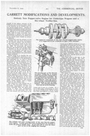
The report of a test carried out recently on the new engine shows a very favourable consumption of fuel and water, especially when the heavy load carried is taken into consideration. Actually, on the particular test .12.3 tons was carried, 8.3 tons being on the wagon and 4 tons on a trailer. On a run of 92.4 miles, maintaining an average speed of 15.25 m.p.h., 742 lb. of fuel was used and 4,720 lb. of water, which works out at .654 lb. of fuel per ton-mile and 4.16 lb. of water per ton-mile. The dampers were shut for about half the distance and all hills were climbed in top gear, several gradients of the 1-in-10 order having to be negotiated on the somewhat undulating route. The normal engine revolution speed is round about 50 r.p.m., and the steam pressure 250 lb. per sq. in.
This, then, gives a fair idea of the capabilities of the vehicle. The underlying idea behind the introduction of the poppet valve engine is an attempt to make the power unit more troubleproof in unskilled hands. Drivers have been known, when overrunning down steep hills, to use the reverse gear as a brake, imposing exceedingly heavy stresses upon the reciprocating parts. With a poppet-valve engine, of course, this cannot occur.
The engine is made u of four sections, the two cylinders lying side by side with the valves inclined at 90 degrees to each other and operated from a camshaft ,,running longitudinally beneath the centre line of the unit. The other three sections consist of a crankcase and two intermediate castings, the forward one of which contains the stuffing boxes, the rear one forming the cnosshead guide. The crankshaft itself is balanced and is built up with hardened and ground crank-pius. It is carried in taper roller bearings in the main crankcase casting, which completely enclosei all the moving parts. lila& side of the case has large-diameter spigoted clovers which enable easy access to the various components to be obtained. This casting—the crankcase— also houses a cross-shaft lying beneath and forward of the crankshaft centre line, which provides the drive, through a. pair of spiral spur gears to the longitudinally arranged camshaft. Gears are employed for driving the cross-shaft. A virtual idler wheel, however, has hn eccentric which is coupled to the water pump, this wheel running at one-third engine speed. The 'hole of the distribution drive is enclosed and runs in oil.
Two stuffing boxes are used for each of the piston rods, the idea being to avoid any molecules of water being transferred from the cylinder along the crosshead and into ,teth crankcase, thereby polluting the oil and decreasing its lubricating properties. Actually, no parts of the piston rods which are in contact with the steam within the cylinders pass beyond the second gland, the
intervening space between this gland and the forward one being utilized as a trap for any condensed steam.
A point of note is the manner in which access can he gained to the gland nuts. On each side of the unit there are covers (easily detachable) and measuring no less than 7 ins. by 9 ins., so that a spanner can he used quite conveniently. The piston-connecting-rod assembly is a very fine job, both ends (i.e., the piston head and the crossheads) being attached to the rod by taper joints, thereby eliminating the cotter-type of attachment. The connecting rods follow marine-type practice, being steel stampings with the journals lined with bronze-backed white metal, with shims for adjustment. Oil is picked up from the base by two holes, one in the rod and the other in the cap.
The valves are operated by adjustable roller-ended tappets which bear directly on to the valve stems. The valves themselves are of the flat-face type and work in detachable guides, the top Ends of which also form the pressure seal. Thus, when wear takes place, the seatings and the guides becotne equally worn, and replacement can be effected for both points at one operation ; the guides, in cidentally, are pressed into the cylinder casting and ctm be withdrawn by the usual bolt-and-distanee-piece method. Another item of interest so far as maintenance work is concerned is the fact that the camshaft and its drive are made in two parts, which are connected by means of a groove and tongue joint ;• thus the gear drive, an item which should never wear, materially, need not be replaced when it is necessary to replace the eamahaft.
So far as the cab arrangement is concerned, a distinct improvement has been effected in bunker capacity room for the stoker and visibility of the driver. Actually, the driver's seat has been moved forward until he now sits alongside, the boiler and, wi tout leaning forward unduly, can see the road immediately in front of him.
Turning no* to a consideration of the trolley-bus. ¶Lhis particular vehicle has been introduc d in order to provide a double-deck body with comparatively low weights for each of the wheels to carry. As might be expected, the frame is of the low-loading type with kick-ups over both the front and rear axles. With a mean wheelbase of 15 ft. 6 ins, and a track both front and rear of 6 ft. li ins., the turning circle is as small as 53 ft. diameter—no mean achievement when it is .realized that the virtual wheelbase from front to rear wheels respectively is 17 ft. 6 ins. The overall length of the complete vehicle is 25 it. 10. ins.
The power unit is a Bull motor of 60 h.p. double wound, arranged with series-parallel control. This means, of course, that there are, in effect, two motors on the one armature shaft which can be run in series or parallel, thereby providing variations in torque and speed. The motor is of the ventilated type, giving 60 h.p. at 1,060 r.p.m. at one hour rating and is in accordance with B.E.SA. specification. The commutation is claimed to be absolutely sparkless at any load up to 250 amperes with 33 per cent. field diversion. The frame and end brackets and all revolving parts, except the shaft and electrical components, are of cast-steel; to eastiron is used in the construction. All windings are of copper strip insulated with asbestos, whilst the armature coils are insulated with thick mica troughs, taped on.
The motor is housed in the frame (at a point some 5 ft.-6 ft. from the front) 'by means of east-Steel brackets attached to the side of the motor easing and the frame respectively. Thus, to remove the power unit it is merely necessary to uncouple the electrical connections and a flexible joint at the rear of the shaft, and remove the bracket bolts, when the unit will either lift upwards or drop downwards as desire3.
The axle reduction ratios are each 9i' to 1. The controller housed beneath the front seat (in the cab) provides 10 speeds, six of which are " stopped " by the pedal-type controller action. During the first three stops the motors are in series with resistance "in." The resistance is cut out when the third stop is reached. The current is then changed over to parallel with the resistance "in," and is cut out at the fifth stop. For the sixth stop the field diversion is brought in, thereby providing the maximum power. In the controller itself, the main and reversing barrels are arranged so that the reverse drum cannot be moved unless the main controller is in the " off " position.
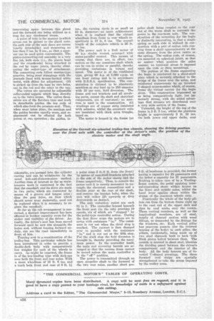
The power is transmitted through an open propeller shaft to the forward of the two rear axles, another short pro _ peller shaft being coupled to the rear end of the worm shaft to transmit the power to the rearmost axle. The construction of the mounting for the bogie is distinctly interesting, in that a single spring on each side is utilized in conjunction with a pair of radius rods running from a shaft approximately at the same distance from the pivot centre as the spring. The radius rods, of course, rre mounted on spherical joints, so that no matter what position the axles assume, no torsional stress is imposed upon the rods or their mountings.
The portion of the frame supporting the bogie is reinforced by a sheet-steel plate which is securely, attached to the bridge of the frame over the axles, and reinforced transversely by an inverted U-shaped cross-member which, of course, forms the virtual carrier for the bogie pivot. This construction impressed us as being comparatively light, but immensely strong, with the added advantage that stresses are distributed over a very wide section of the frame.
Unloaded, the height of the top of the frame is 2 ft. 5 ins., whilst the platform height is approximately 2 ft. 10 ins. On both lower and upper decks, over 6 ft. of headroom is provided, the former having a capacity for 28 passengers and the latter a capacity for 27 passengers. Braking is taken care of by a Westinghouse system, the pedal applying internal-expanding shoes within drums on the front and middle axles, whilst the hand lever applies shoes within the drums of the rearmost wheels only.
Practically the whole of the body pillars run from the bottom frame right up to the cant rail of the upper deck and then by roof sticks over the crown. These vertical members, as well as the longitudinal members, are a steel, mostly of channel section with wood fillings, as demanded by the fittings for the windows, etc. Each vertical pillar has generous gussets (for the irternal bracing of the body) to each pillar, the pillars, incidentally, being made up of two steel channels hack to back 'with flitch plates bolted between them. The outside is covered in sheet steel, likewise the dividing panel between the eriver's compartment and the interior of the body. All the body bearers are of inverted 1_7-shaped pressings. The three forward roof strips are specially strengthened to take the stress imposed by the trolley arms.