


A Low-tension Sparking Plug
Page 54
If you've noticed an error in this article please click here to report it so we can fix it.
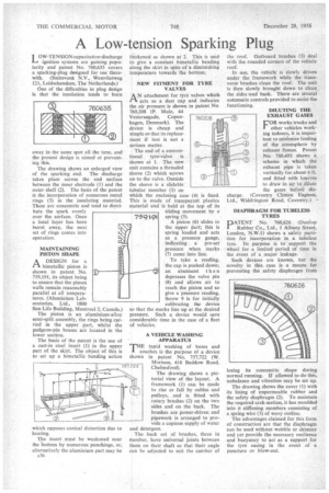
LOW-TENSION capacitative-discharge ignition systems are gaining popularity and patent No. 760,635 covers a sparking-plug designed for use therewith. (Smitsvonk N.V., Westvlietweg 121, Leidschendam, The Netherlands.)
One of the difficulties in plug design is that the insulation tends to burn away in the same spot all the tune, and the present design is aimed at preventing this.
The drawing shows an enlarged view of the sparking end. The discharge takes place across the end surface between the inner electrode (i) and the outer shell (2). The basis a the patent is the incorporation of numerous metal rings (3) in the insulating material. These arc concentric and tend to distri bute the spark evenly over the surface. Once a local layer has been burnt away, the next set of rings comes into operation.
MAINTAINING PISTON SHAPE
A DESIGN for a il bimetallic piston is shown in patent No. 759,191, its object being to ensure that the piston walls remain reasonably parallel at all temperatures. (Aluminium Laboratories, Ltd., 1800 Sun Life Building, Montreal 2, Canada.)
The piston is an aluminium-alloy semi-split assembly, the rings being carried in the upper part, whilst the gudgeon-pin bosses are located in the lower section.
The basis of the patent is the use of a cast-in steel insert (1) in the upper part of the skirt. The object of this is to set up a bimetallic bending action which opposes conical distortion due to heating.
The insert must be weakened near the -bottom by numerous punchings, or, alternatively the aluminium part may be
A36 thickened as shown at 2. This is said to give a constant bimetallic bending along the skirt in spite of 'a diminishing temperature towards the bottom.
NEW FITMENT FOR TYRE VALVES
A N attachment for tyre valves which ti acts as a dust cap and indicates the air pressure is shown in patent No. 760,208 (P. Mule, 44 Vestersogade, Copenhagen, Denmark). The device is cheap and simple so that its replacement if lost is not a serious matter.
The end of a conventional tyre-valve is shown at I. The new unit contains a threaded sleeve (2) which screws on to the valve. Outside the sleeve is a slidable tubular member (3) on which the enclosing case (4) is fixed. This is made of transparent plastics material and is held at the top of its sliding movement by a spring (5).
A piston (6) slides in the upper part; this is spring loaded and acts as a pressure gauge, indicating a pre-set pressure when marks (7) come into line.
To take a reading, the cap is pushed down; an abutment then depresses the valve pin (8) and allows air to reach the piston and so give a pressure reading. Screw 9 is for initially calibrating the device so that thc marks line up at the desired pressure. Such a device would save considerable time in the case of a fleet of vehicles.
A VEHICLE WASHING APPARATUS
THErapid washing of buses and coaches is the purpose of a device shown in patent No. 757,722 (W. Morison, 416 Baddow Road, Chelmsford),
The drawing shows a pictorial view of the layout. A framework (I) can be made to rise or fall by cables and pulleys, and is fitted with rotary brushes (2) on the two sides and on the back. The brushes are power-driven and pipework is arranged to provide a copious supply of water and detergent.
The back set of brushes, three in number, have universal joints between them on their shaft so that their angle can be adjusted to suit the camber of the roof. Outboard brushes (3) deal with the rounded corners of the vehicle roof.
In use, the vehicle is slowly driven under the framework while the transverse brushes clean the roof. The unit is then slowly brought down to clean the sides land back. There are several automatic controls provided to assist the functioning.
DILUTING THE EXHAUST GASES
FOR works trucks and other vehicles working indoors, it is important to mitiimize fouling of the atmosphere by exhaust fumes. Patent No. 760,493 shows a scheme in which the exhaust pipe is taken vertically for about 6 ft. and fitted with louvres to draw in air to dilute the gases. before discharge. (Coventry Climax Engines, Ltd., Widdrington Road, Coventry.) —
DIAPHRAGM FOR TUBELESS TYRES
PATENT No. 760,626 (Dunlop Rubber Co., Ltd., 1 Albany Street, London, N.W.1) shows a safety partition for incorporation in a tubeless tyre. Its purpose is to support the wheel for a limited period of time in the event of a major leakage.
Such devices are known, but the novelty in this case is a means for preventing the safety diaphragm from losing its concentric shape during normal running. If allowed to do this, unbalance and vibration may be set up.
The drawing shows the cover (1) with its lining of impermeable rubber and the safety diaphragm (2). To maintain the required arch section, it has moulded into it stiffening members consisting of a spring wire (3) of wavy outline.
The advantages claimed for this form of construction are that the diaphragm can be used without wobble or shimmy and yet provide the necessary resilience and buoyancy to act as a support for the tyre casing in the event of a puncture or blow-out.