


Patents Completed.
Page 22
If you've noticed an error in this article please click here to report it so we can fix it.
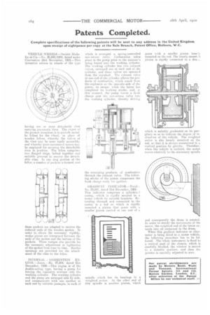
VEHICLE WHEELS.—Societi Michelin et Cie.—No. 26,699/1909, dated under Convention 28th November, 1908.—This invention relates to wheels of the type having one or more detachable rims carrying pneumatic tires. The object of the present invention is to provide metallic fakes for the wheel, in place of wooden felloes, whereby the valves of the tires may be more easily accessible, and whereby more-convenient means may be employed for securing the detachable rims in position. The felloe comprises two flanged rings, bolted together and suitably grooved to receive the detachable rims. In one ring portion of the felloe, a number of pockets is formed, and
these pockets are adapted to receive the reduced ends of the wooden spokes. In order to obtain the necessary rigidity, wedge pieces are interposed between the ends of the spokes and the bottom of the pockets. These wedges also provide for the necessary adjustment or tightening of the spokes from time to time. Similar openings are provided for the attach ment of the rims to the felloe.
INTERNAL COMBUSTION ENGINE.—Jones.—No. 27,804, dated 21st December, 1908.—This engine is of the double-acting type, having a pump for forcing the explosive mixture into the working cylinder. The working cylinder and the pump are arranged side by tide, and communicate with one another at each end by soitabie passages, in each of
which is arranged a spring-controlled non-return valve. Carburation Lakes place in the pump prior to the mixture's being forced into the working cylinder. The working cylinder has two exhaust valves, arranged one at each end of the cylinder, and these valves are operated from the camshaft. The exhaust valve at one end of the cylinder allows the products of combustion, w hieh result from the explosion on the opposite side of the piston, to escape, when the latter has completed its working stroke, and, at this moment, the pump forces a frcali charge past the non-retorn valve int., the working cylinder, thereby driving
the remaining products of combustion through the exhaust valve. The following stroke of the piston compresses the fresh charge ready for ignition.
GRADIENT 3NDICATOR.—Twidlo. No. 29.841, dated 21st December, 1909.This indicator comprises a cylindrie:.I casing, which is rigidly secured to a motor vehicle by suitable brackets. Extending through and connected to the casing is a rod on which is rigidly mounted a pinion that gears with a smaller pinion carried at one end of a
spindle which has its bearings in a weighted sector. At the other end of this spindle is another pinion, which gears with a smaller pinion loosely mounted on the rod. The loosely-mount( cl pinion is rigidly connected to a dru:.i,
which is is suitably graduated on its periphery SO as to indicate the degree of inclination of the vehicle. The weighted sector is also loosely mounted on the rod, so that it is always maintained in a vertical position by gravity. Therefore, when the vehicle is inclined, the sector moves relatively to the stationary spindle
and consequently the drum is rotated In order to steady the movements of the sector, the weighted end of the latter ex. tends into oil contained in the drum.
When this gradient indicator or clinometer is being fitted to a motor vehicle, the following procedure has to be followed. The whole instrument. is fixed to a vertical part of the chassis, which is carefully levelled, the window is moved to a suitable position, and then the pointer is eaiefully adjusted to zero.