


Contributions from Drivers and Mechanics.
Page 20
Page 21
If you've noticed an error in this article please click here to report it so we can fix it.
TEN SH11,k,INGS 'WEEKLY for the Best Communication Received, and One Penny a Line of ten words for any
thing else published.
Drivers of commercial-motor vehicles and tractors, and mechanics and foremen of garages or shops, are invited to send short contributions on any subject which is likely to Prove of interest to our readers. Workshop tips and smart repairs ; long and successful runs; interesting photographs : all are suitable subjects. Send a post-card, or a letter, or a sketch to us—no matter how short, or how written, or how worded. IVe will "knock it into shape" and prepare sketches, where necessary, before publication. The absence of a sketch does not disqualify for a prize. When writing use one side of the paper only and mention your employer's name as a guarantee of bona fides. Neither your own nor your employer's name will be disclosed. Payment will be made immediately after publication, Address your letters to The Editor, THE Commsacisn MOTOR, 7-15, Rosebery Avenue, London, E.C.
Drivers should note that the entries for the C.M. U.A. Parade and Prize Scheme close on the 7th of May. Full particulars have already appeared in the issue of this journal for the 7th inst. In the section for THE 03)1MP:101AI. Mows Cup, the mileage and vehicle-age limits of the individual sections do not apply—see page 151.
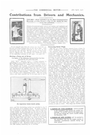
Making a Pump out of Scrap.
The sender of the following communication has been awarded the 10s. prize this week.
[695] " 11.J." (Strood) writes :—" 1 have pleasure in submitting to you a sketch [We have had this redrawn.— En.] and particulars of a simple form of pump which I made entirely out of scrap. I wanted something to test a small boiler with, and I got hold of two old wheel valves, and disconnected the spindles from the valves. 1 made them into check valves by screwing down two stop pieces in the place of these spindles. The next thing to procure was a T piece and a diminishing socket. The two check valves were then screwed one on to each end of the T piece. and the diminishing socket was attached to the T piece by means of an ordinary nipple. To make a stuffing box, I procured a suitable brass plug, whirls I had previously drilled to the same size as the hole in the confleeting nipple, and screwed this into the large end of the diminishing socket. I then made a plunger to suit the hole in this plug, and fitted the whole lot up together with the short, lever and pillar as shown in the rough sketch which I have attached to this communication. I found it quite a simple matter to test the boiler, and I was delighted to find that such a simple contrivance served my purpose so well. Perhaps it may be of use to others who like making something out of nothing."
Protecting Boiler Plugs.
[696] We give below further extracts from a letter by CT.'' (Fulham), part of which we published last week.
The injectors which are fitted to most boilers of the steam-wagon and tractor types are usually of the lifting, automatic, restarting pattern. While the conditions remain favourable, they will, in some cases, work eontimmusly for years without giving any trouble whatever. As a rule, I have not found trouble with the deposit of sediment in these fittings, which is principally due to the fact that the water and steam pass through the cones at such a high speed, that they have a scouring effect
on all the passages. Occasionally, however, sediment does accumulate in the injectors, with the result that, sometimes there is a difficulty in getting them to start for this reason. Frequently, too, it is difficult, to get an injector to start., unless cold water be poured over it to assist in the condensation of the steam in the combining cone. This is a trouble with which practically-all locomotive drivers are only too familiar, and it is always a difficult matter to take an injector down to clean it, and one which calls for considerable care. A simple and quick method of cleaning out one of these fittings, without the removal of the cones, is one that I have used for the past twelve years. I first of all take down the injector, and then I cut wooden plugs to fit into each of the openings, with the exception of one—say, the feedwater inlet. Care must be taken in inserting the wooden plugs not to injure the inside of the openings: they want to be just sufficiently tight to prevent the escape of fluid, hut they need only just be hand tight. The injector should then be placed in such a position that the opening which is not plugged shall be at, the top. Some spirits of salts is then poured into this opening, but care must be taken not to fill it to the top, as 'boiling' soon takes place. When the acid appears to have finished its action upon the sediment, it should be emptied out and a fresh lot poured in. Two or three baths like this should be quite sufficient, and the injector should then be swilled out with water and, finally, with a strong solution of soda in water. This stops any further action of any acid that may have been left, and prevents any chance of pitting taking place. Care, of course, roust be taken not to let any acid find. its way into the boiler, as this will be very harmful. The overflow nozzle should not be used to fill up the injector with the acid, as those fittings which are provided with flap valves would not allow the acid to get into the various oones of the injector. A final tip is, when an injector is refitted, after having been taken down for cleaning, very-great care must be taken that no red lead or other jointing be allowed to get through into the passages. I have known many an injector stoppage which has been eventually traced to the careless making of the joints in this way."
A Tool for Releathering a Clutch.
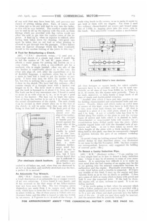
[697] " (Dartford) writes.—"I send you a very-rough sketch of a simple tool which I would like to tell the readers of D. and M.' pages about. It affords a ready means for putting the leather on to a
(-one dutch. This is often a very-difficult job for a mechanic who is single handed; when one side of the now leather is comfortably placed on to the conc, the other side slips off, and, after the expenditure of a lot of doubtful language; a mechanic often has to call in a mate to lend him a hand DO get the leather on properly. I have seen men tie down the leather hit by bit, but this is nothing like a good job. The tool which I show in the sketch [We have had this redrawn..—Em] consists simply of a straight lever with a booked arm hinged on to it. The lever itself is about 15 in. long, and the hook is fastened to it about 4 in. from one end. The hook can be of any convenient size; I found it useful to make it as wide even as 1! in., so as to get a good. hold on the leather. The best w ay to begin the operation of fixing the leather is to cut it 1 in. shorter than the actual circumference of the clutch. The ends should then be riveted in their proper place on to the face of the clutch: it will be quite clear that cue side of the lining is then held in position. If the hook part of this special tool he placed over the edge of the leather, and the straight or handle part be placed against the larger edge of the metal cone, the" leather may readily be prised on to the face, and so riveted into position. If two of these tools are used, a mostobstinate leather, never mind how stiff it is, may he prised into position, but I have always found that one is sufficient in all ordinary eases. Most leathers are soaked in oil before use, and, when they are shortened by an inch as described, and carefully stretched over the face, a perfect fit is assured."
For obstinate clutch leathers.
An Adjustable Tap Wrench.
[698] " H.S." (Luton) writes:" I send you herewith a rough description of an adjustable tap or reamer wrench of my own contriving. I have found it very handy, and it has occurred to me that many of my fellow-readers may not have seen the idea. The two clamping pieces themselves are made from 4 in. square steel, and the ends, which have to form the two hendles, are filed round to admit. 5-16th in. One of these pieces is drilled with two clearance holes, and the other is tapped to rake two 3-1.6th in. set screws. A V-groove is yet in each of the clamp. I made wing heads to the screws: so as to make it easier to get hold of them with my fingers. For these I used two ordinary cheese-headed set screws and brazed some bits of 1-16th in. lagging plate into the screw cuts in the heads. This adjustable wrencIi makes a much-better job ihan hexagon or square heads, for which suitable spanners have to be provided, and it can he ustel comfortably on all sizes of taps from 3-16th in. to 3-8th in., as it, of course, fits the square ends perfectly. There is no need, moreover, Lo keep handy a large stock of all sizes of single and double-ended wrenches_ " Another idea which I have put into practice is one for holding cheese-headed and snap-headed bolts and setstrews. 'Us:wily, fitters ;And others make an awful mess SereWS of this kind, when they have to hold them in viee, even when lead clamps are used. All that is wanted is a piece of iJ in. steel plate, about in. wide and 5 in. long. A row of suitable holes has then to be drilled along the middle of the plate to suit the various types of Screws and bolts which it is desired to hold ; cheese-headed or snap-headed bolts will require flat or rutted-bottom holes drilled partly into the plate, whilst it suitable tapped holes will held the threaded ends of set
.serews and bolts. A cut is then taken up nearly the whole length of the plate with a thick hacksaw. Anything held in this plate, can then be conveniently clamped in position between the jaws of an ordinary workshop vice."
FA special clamp for holding screwed bolts, of somewhatsimilar design to that described above, was illustrated in mu: issue for the 9th November, 1909. On that occasion our correspondent, however, only suggested the holding of screwed parts.—En.] To Detect a Leaky Induction Pipe.
[699] " MW.'' (Durham) writes:—" I am sending you a very simple hintas to how to detect a leaky induction pipe. I hope it may be of interest to some of your many readers. It is surprising how difficult it is to make up your mind that the bad running of an engine may be due to air getting into the mixture somewhere between the carburetter and the engine. Practically everything is, as a rule, tried before such a trouble is suspected. If I have any trouble of this kind, I start up the engine and then throttle down so as to run as slowly as possible. I then get a piece of cloth or waste which is damp with, petrol and hold it over the suspected joint. If the leak he there, the engine will, at once, increase its speed. Tt is an unfailing method.
" A tip worth noting is that, when the setscrew which holds a hollow gudgeon pin in position is provided with a simple pointed end which screws into the pin, it. is as well to fit a. new pin whose end shall protrude into the hollow !mist of the pin. A split pin may then easily 'be inserted, and the setscrew thus be positively locked."